Light merging/branching device, bidirectional light propagation device, and light transmission/reception system

a light merging/branching and light transmission technology, applied in multiplex communication, instruments, cladded optical fibres, etc., can solve the problems of increasing the loss budget of allowance transmission and the inability to normally receive up-signals, so as to reduce the loss amount, increase the loss budget, and reduce the loss of the coupling loss of up-signals

Active Publication Date: 2014-07-03
NIPPON TELEGRAPH & TELEPHONE CORP
View PDF1 Cites 36 Cited by
  • Summary
  • Abstract
  • Description
  • Claims
  • Application Information

AI Technical Summary

Benefits of technology

[0047]According to the present invention, the splitting of the down-signal and the coupling of the up-signals are realized by the same optical device, and the coupling loss of the up-signals is reduced, thereby making it possible to obtain an effect similar to that in a case of increasing the loss budget equivalently by the reduced loss amount.

Problems solved by technology

However, the PON system has been already put into practice, but, expansion of an allowance transmission loss budget is still demanded.
In a case of arranging the front-side optical amplifier in the accommodation station for use, however, when a strenuous burst optical signal is incident to the front-side optical amplifier, there occurs a problem that an optical signal exceeding an input dynamic range reaches the receiver in the accommodation station, the up-signal cannot be normally received.

Method used


Image

  • Light merging/branching device, bidirectional light propagation device, and light transmission/reception system
  • Light merging/branching device, bidirectional light propagation device, and light transmission/reception system
  • Light merging/branching device, bidirectional light propagation device, and light transmission/reception system

Examples


embodiment 1

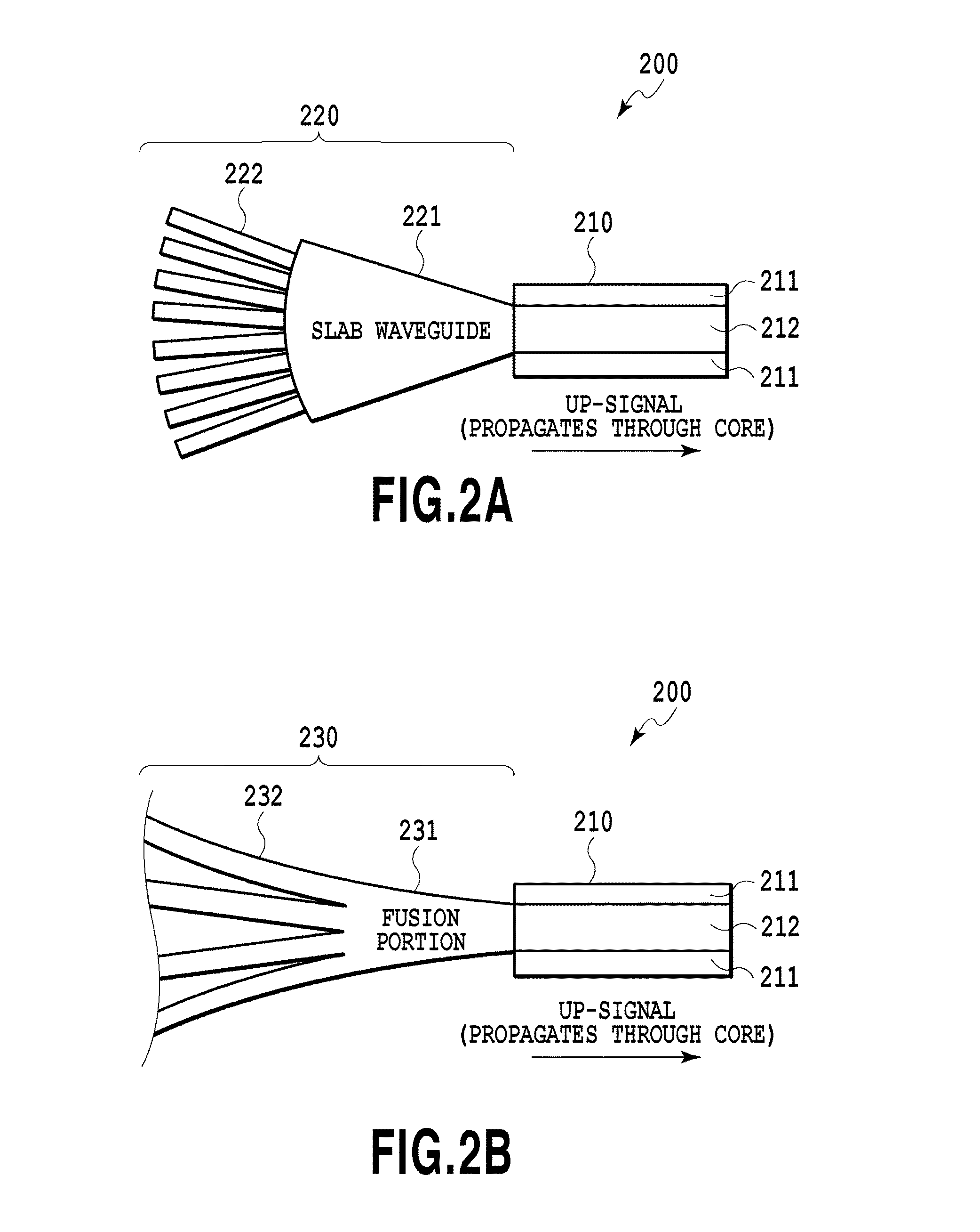
[0086]FIG. 3 shows an optical coupling / splitting device 300 according to an embodiment 1 in the present invention. FIG. 3 shows the optical coupling / splitting device 300 that is provided with a dual mode fiber (DMF) 310 and a PLC 320 that is connected to the DMF 310. The DMF 310 is provided with multi-mode (MM) clads 311 and an MM core 312, and the MM core 312 is provided with single mode (SM) clads 313 and an SM core 314. The PLC 320 is provided with a slab waveguide 321 and SM waveguides 322 that are connected to the slab waveguide 321. It should be noted that FIG. 3 exemplifies a case of using the PLC, but a fusion SMF waveguide shown in FIG. 2B may be used.

[0087]The DMF 310 is an optical fiber that can be used for both of SM transmission and MM transmission. In the DMF 310, the SM clads 313 and SM core 314 for SM transmission form the MM core 312 for MM transmission, and the MM clads 311 for MM transmission are formed outside of the MM core 312.

[0088]FIG. 4A and FIG. 4B each sho...

embodiment 2

[0092]FIG. 5 shows a system 500 using an optical coupling / splitting device 520 according to an embodiment 2 in the present invention. FIG. 5 shows the system 500 that includes subscriber devices 110, optical splitting device 120, and an accommodation station 510, wherein the accommodation station 510 is provided with an optical coupling / splitting device 520, and an OLT 530 that includes a transmitter 531 and a receiver 532.

[0093]The optical coupling / splitting device 520 shown in FIG. 5 has the configuration of connecting an optical coupling / splitting portion 521 formed of the optical coupling / splitting device 300 according to the embodiment 1 and a wavelength multiplexing / demultiplexing device 522 for multiplexing / demultiplexing up and down-signals through a DMF 523. As shown in FIG. 5, the wavelength multiplexing / demultiplexing device 522 and the transmitter 531 are connected through an SMF 540, and the wavelength multiplexing / demultiplexing device 522 and the receiver 532 are conn...

embodiment 3

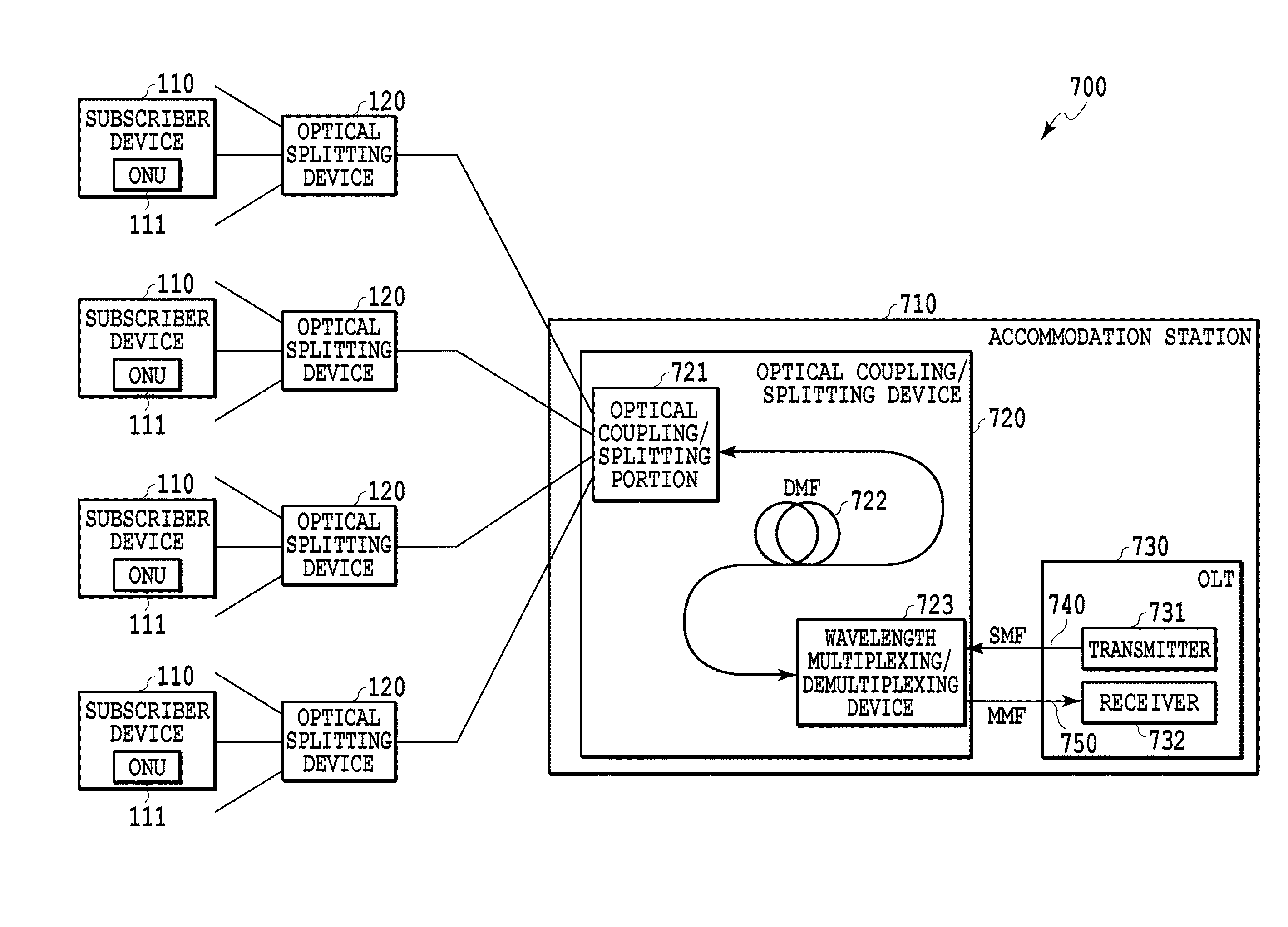
[0100]FIG. 7 shows an optical transmit-receive system 700 according to an embodiment 3 in the present invention. FIG. 7 shows the system 700 that includes the subscriber devices 110, the optical splitting devices 120, and an accommodation station 710, wherein the accommodation station 710 is provided with an optical coupling / splitting device 720, and an OLT 730 that includes a transmitter 731 and a receiver 732. The optical coupling / splitting device 720 includes an optical coupling / splitting portion 721 formed of the optical coupling / splitting device 300 according to the embodiment 1, and a wavelength multiplexing / demultiplexing device 723 that is connected to the optical coupling / splitting portion 721 through a DMF 722.

[0101]In the optical coupling / splitting device 720, the DMF 722 is configured such that a diameter of an SM clad is reduced in a tapered shape in direction from the optical coupling / splitting portion 721 to the wavelength multiplexing / demultiplexing device 723. FIG. ...


PUM


Abstract

The present invention relates to an optical coupling / splitting device that realizes the splitting of a down-signal and the coupling of up-signals by the same optical device, and reduces coupling losses of the up-signal. An optical coupling / splitting device in the present invention comprises an optical coupling / splitting means for coupling a plurality of up-signals in a multi-mode for output and splitting a down-signal in a single mode for output, and a two-way optical propagation means for propagating the up-signal that is output from the optical coupling / splitting means in a multi-mode for output and propagate the down-signal in a single mode to be output to the optical coupling / splitting means.

Description

TECHNICAL FIELD[0001]The present invention relates to an optical coupling / splitting device, an two-way optical propagation device and an optical transmit-receive system that are used in an optical subscriber network.BACKGROUND ART[0002]In the optical subscriber network system, a passive optical network (PON) system that is standardized in IEEE or ITU-T is widely adopted. The PON system is configured such that optical network units (ONU) that are arranged respectively to a plurality of subscriber devices are connected to an optical line terminal (OLT) arranged in the accommodation station through optical splitting device and one optical fiber arranged inside and outside the accommodation station.[0003]In the PON system, an up-signal and a down-signal are transmitted bi-directionally on the same optical fiber by different wavelengths. The down-signal is a successive signal formed by multiplexing signals that are output from the OLT by using a time division multiplexing (TDM) technolog...

Claims


Application Information

Patent Timeline
Patent Type & Authority Applications(United States)
IPC IPC(8): H04B10/27
CPCG02B6/4215G02B6/02047G02B6/03633G02B6/125G02B6/2808G02B6/2813G02B2006/12109H04B10/27G02B6/30G02B6/0283G02B6/12007G02B6/14G02B6/2821H04B10/272H04J14/0245H04J14/0242H04J14/0249
Inventor FUJIWARA, MASAMICHISUZUKI, KENICHIYOSHIMOTO, NAOTOOGUMA, MANABUWATANABE, TOSHIOTAKAHASHI, HIROSHITANOBE, HIROMASAKITOH, TSUTOMU
Owner NIPPON TELEGRAPH & TELEPHONE CORP
Why Eureka
Try Eureka