Self injection locked phase locked looped optoelectronic oscillator

a technology of optoelectronic oscillators and phase locking loops, which is applied in the direction of digital transmission, pulse automatic control, radio-over-fibre, etc., can solve the problems of not providing a stable signal alone, not achieving a sufficiently stable signal, and not achieving pll noise reduction

Active Publication Date: 2014-07-03
SYNERGY MICROWAVE CORP
View PDF4 Cites 115 Cited by
  • Summary
  • Abstract
  • Description
  • Claims
  • Application Information

AI Technical Summary

Benefits of technology

[0011]One aspect of the disclosure provides an opto-electronic oscillation circuit for sustaining an oscillating optical signal. The opto-electronic oscillation circuit may include a self injection locking component configured to receive a first portion of the oscillating optical signal, and further comprising a fiber optic delay line over which the optical signal propagates. The opto-electronic oscillation circuit may also include a self phase locked loop component configured to receive a second portion of the optical signal. The self phase locked loop component may further include at least two fiber optic cables over which the optical signal propagates, and at least one phase detector coupled to the fiber optic cables and configured to determine a difference in phase between a signal propagating over one of the fiber optic cabl...

Problems solved by technology

While the currently known advances in phase noise reduction are effective at raising the quality factor and increasing stability for oscillators, these advances alone do not provide a stable enough signal to satisfy some oscillat...

Method used


Image

  • Self injection locked phase locked looped optoelectronic oscillator
  • Self injection locked phase locked looped optoelectronic oscillator
  • Self injection locked phase locked looped optoelectronic oscillator

Examples


Embodiment Construction

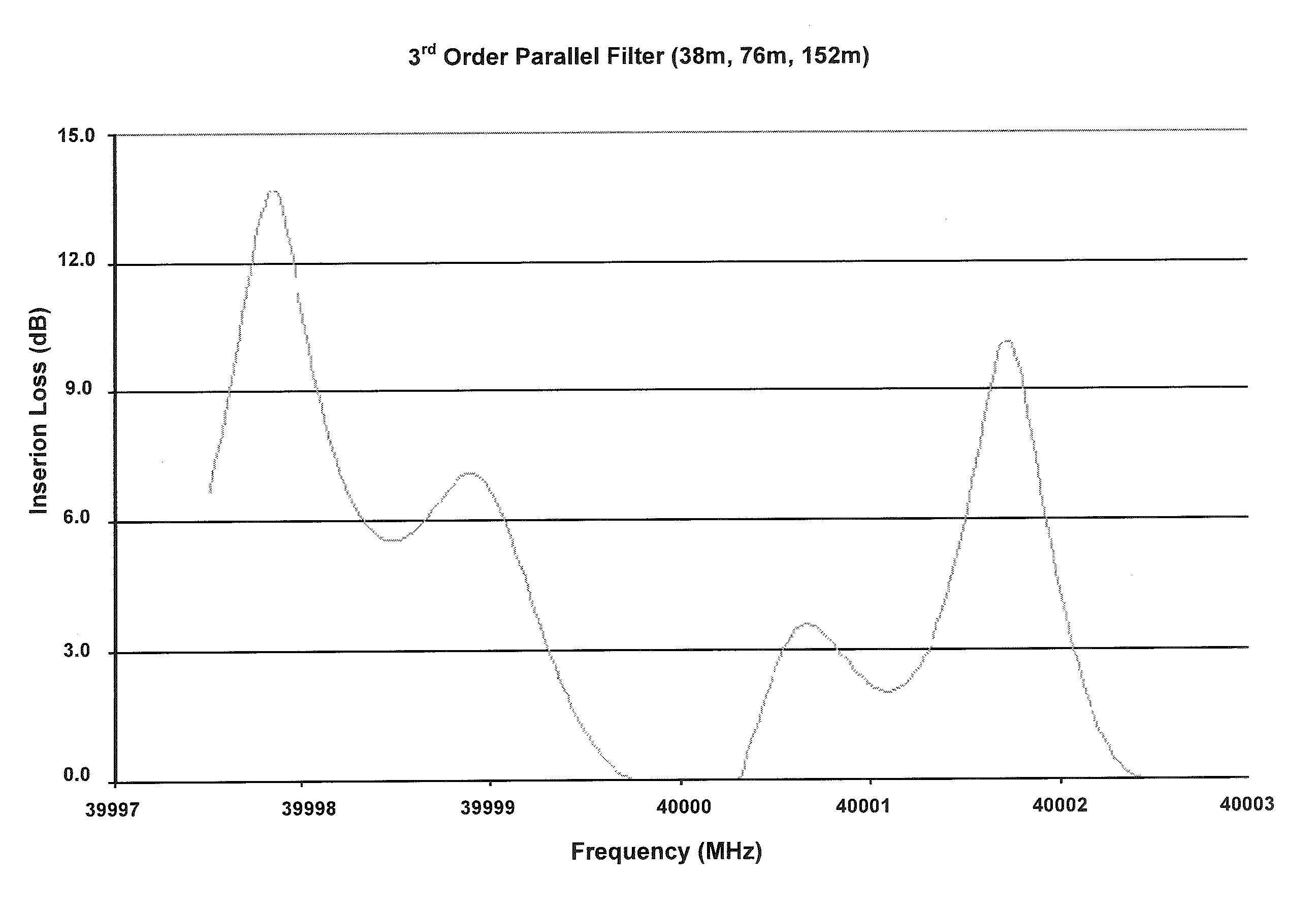
[0037]The present invention achieves frequency and phase stability required for both a narrower channel resolution than that achieved by present systems (due to, e.g., reduction of phase noise) as well as a more precisely locked frequency (due to, e.g., reduced temperature sensitivity). As a result, more data (e.g., fidelity data) is, for example, able to be transmitted over a given bandwidth, all while reducing error rates for such transmitted data.

[0038]One object of the disclosure is to provide an oscillation system that allows for converting light energy into stable, spectrally pure RF / microwave reference signals having reduced close-to-carrier (offset frequency of 1 MHz or less) phase noise. Another object of the disclosure is to provide an oscillation system in which it is possible to maintain a precisely locked phase while still maintaining a clean close-in to carrier phase noise.

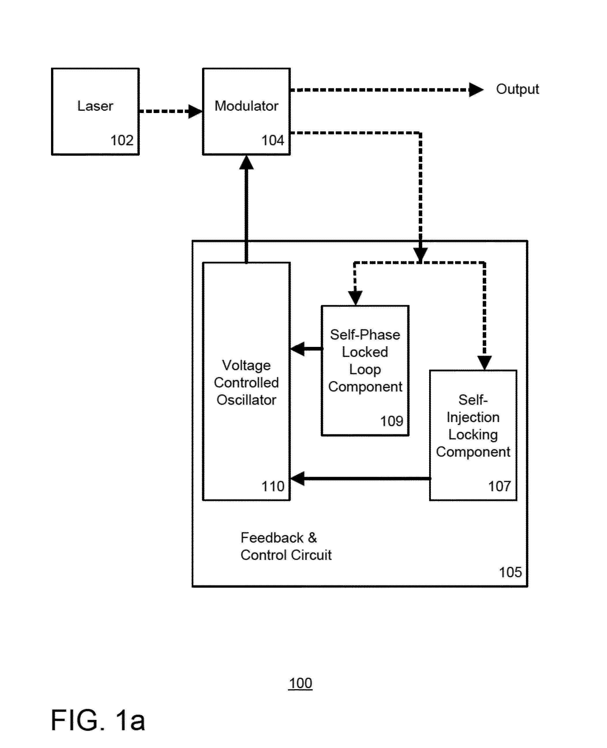
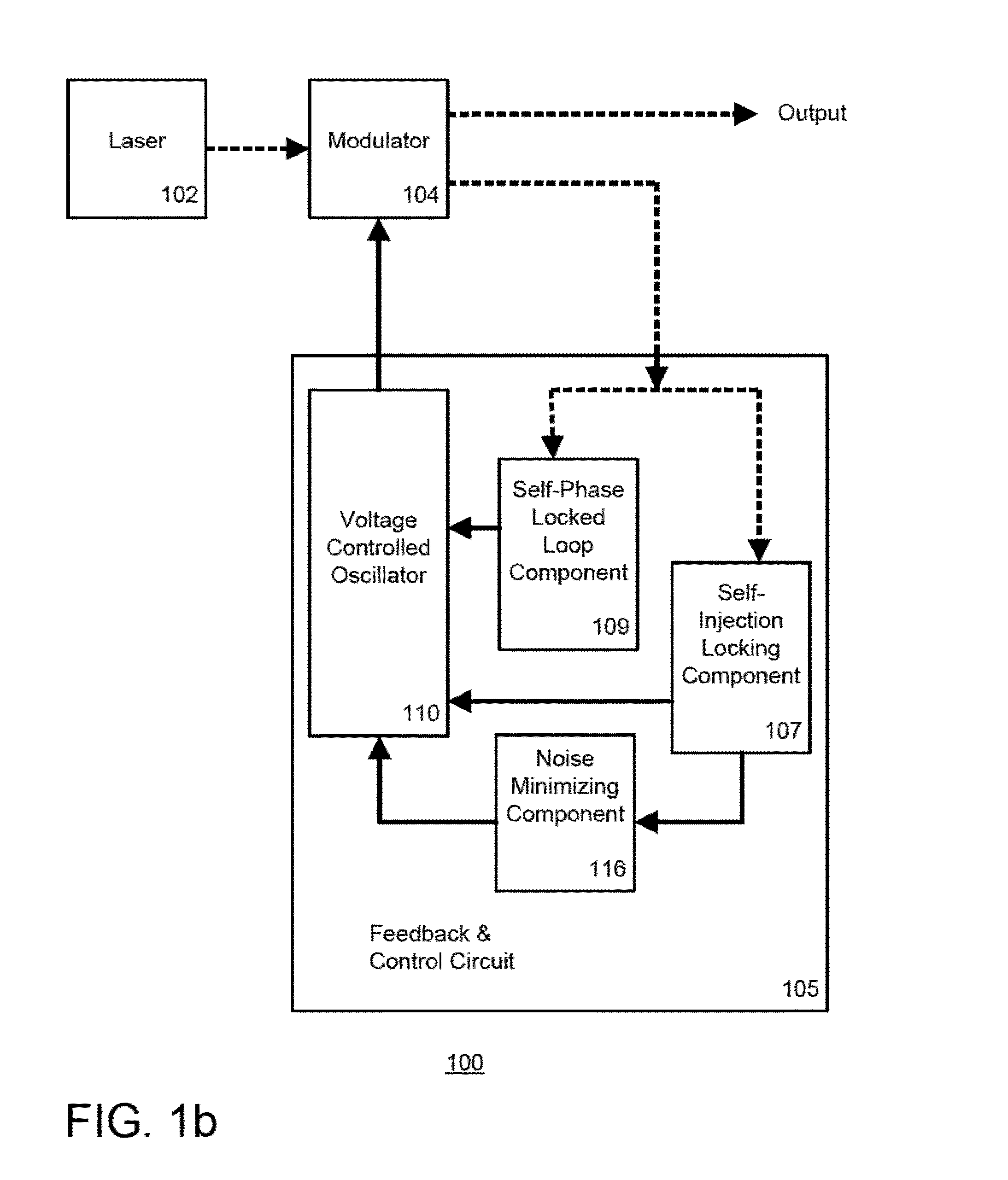
[0039]Yet another object of the disclosure is to provide an optoelectronic oscillation system hav...


PUM


Abstract

Aspects of the disclosure relate generally to a circuit for sustaining an radio frequency (RF) modulated optical signal. The circuit may comprise a self injection locking component having a fiber optic delay line over which a portion of the optical signal propagates. The circuit may also comprise a self phase locked loop component having at least two fiber optic cables having different lengths and over which another portion of the optical signal propagates and a phase detector coupled to the at least two fiber optic cables and configured to determine a phase difference between the signals propagating over one of the respective fiber optic cables. The circuit may further comprise a voltage controlled oscillator configured to generate a stable oscillating signal in response to signals generated by each of the self injection locking and self phase locked loop components, the stable oscillating signal being configured to sustain the optical signal.

Description

CROSS-REFERENCE TO RELATED APPLICATIONS[0001]The present application claims the benefit of the filing date of U.S. Provisional Patent Application No. 61 / 746,919 filed Dec. 28, 2012, the disclosure of which is hereby incorporated herein by reference.BACKGROUND[0002]This disclosure is directed to a system and method for controlling an optoelectronic oscillator (“OEO”). In a preferred embodiment, the OEO is capable of producing repetitive electronic sine or any arbitrary wave and / or electrically modulated continuous wave or pulsed optical signals.[0003]OEOs are an optical and electronic hybrid device and use optical modulation to produce electrical output oscillations in RF and microwave frequencies that can exhibit narrow spectral line widths and ultra low phase noise in comparison with the conventional RF and microwave signal sources. Optical resonators intrinsically can support variation of resonant modes of light called whispery gallery modes (WGMs), hence many oscillation modes ca...

Claims


Application Information

Patent Timeline
IPC IPC(8): H04B10/508
CPCH04B10/508H03L7/00H04B2210/006H03B17/00H04B10/2575H01S3/1109H01S3/302H04L7/0041H04L7/033H04L7/0337H04L7/0037H04B10/00H04L7/0075H01S3/0085H01S3/06754H01S3/136H01S3/10
Inventor PODDAR, AJAY KUMARROHDE, ULRICH L.DARYOUSH, AFSHIN S.
Owner SYNERGY MICROWAVE CORP
Why Eureka
Try Eureka