Telescopic shaft

a telescopic shaft and telescopic technology, applied in the field of telescopic shafts, can solve the problems of reduced durability of a telescopic shaft, increased and difficulty in forming grease reservoirs, so as to reduce wear or deformation of the tooth surface and improve the durability of the telescopic sha

Active Publication Date: 2014-07-03
NSK LTD
View PDF4 Cites 9 Cited by
  • Summary
  • Abstract
  • Description
  • Claims
  • Application Information

AI Technical Summary

Benefits of technology

[0019]According to an aspect of the present invention, one of the curvature radius of the tooth surface of the protruding teeth and the curvature radius of the tooth surface of the tooth grooves is smaller than the other of the curvature radius of the tooth surface of the protruding teeth and the curvature radius of the tooth surface of the tooth grooves. Therefore, the center part of the tooth surface of the protruding teeth in the tooth depth direction comes into contact with the center part of the tooth surface of the tooth grooves in the tooth depth direction, whereby rotational torque is transmitted. Therefore, even when there is a manufacturing error of the protruding teeth and the tooth grooves, the tooth surfaces come into contact at the center position in the tooth depth direction such that th...

Problems solved by technology

However, in a case of a telescopic shaft to be spline-joined, it is difficult to form grease reservoirs in the direction perpendicular to the axial direction, so it is an object to smoothly supply grease to the tooth surfaces.
Also, according to a conventional method in which the tooth surfaces of a male shaft and a female shaft are formed to have a same profile, if an error occurs in the pressure angles of the tooth surfaces of the male shaft and the female shaft due to a manufacturing error of the tooth surfaces, the tooth surfaces of the male shaft and the female shaft locally hit each other, whereby wearing or def...

Method used


Image

  • Telescopic shaft
  • Telescopic shaft
  • Telescopic shaft

Examples


first embodiment

[0029]Hereinafter, a first embodiment of the present invention will be described with reference to FIGS. 1 to 4.

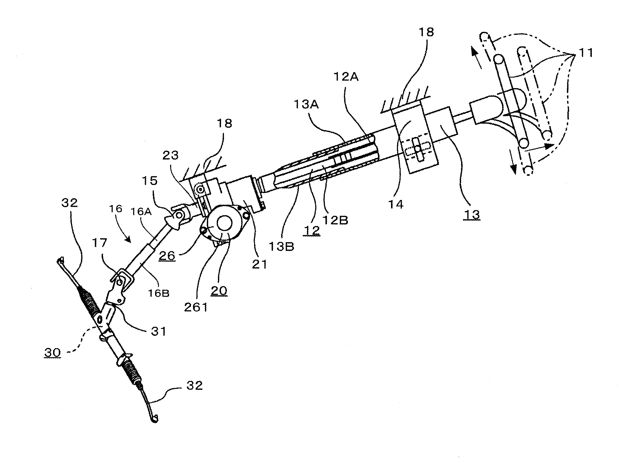
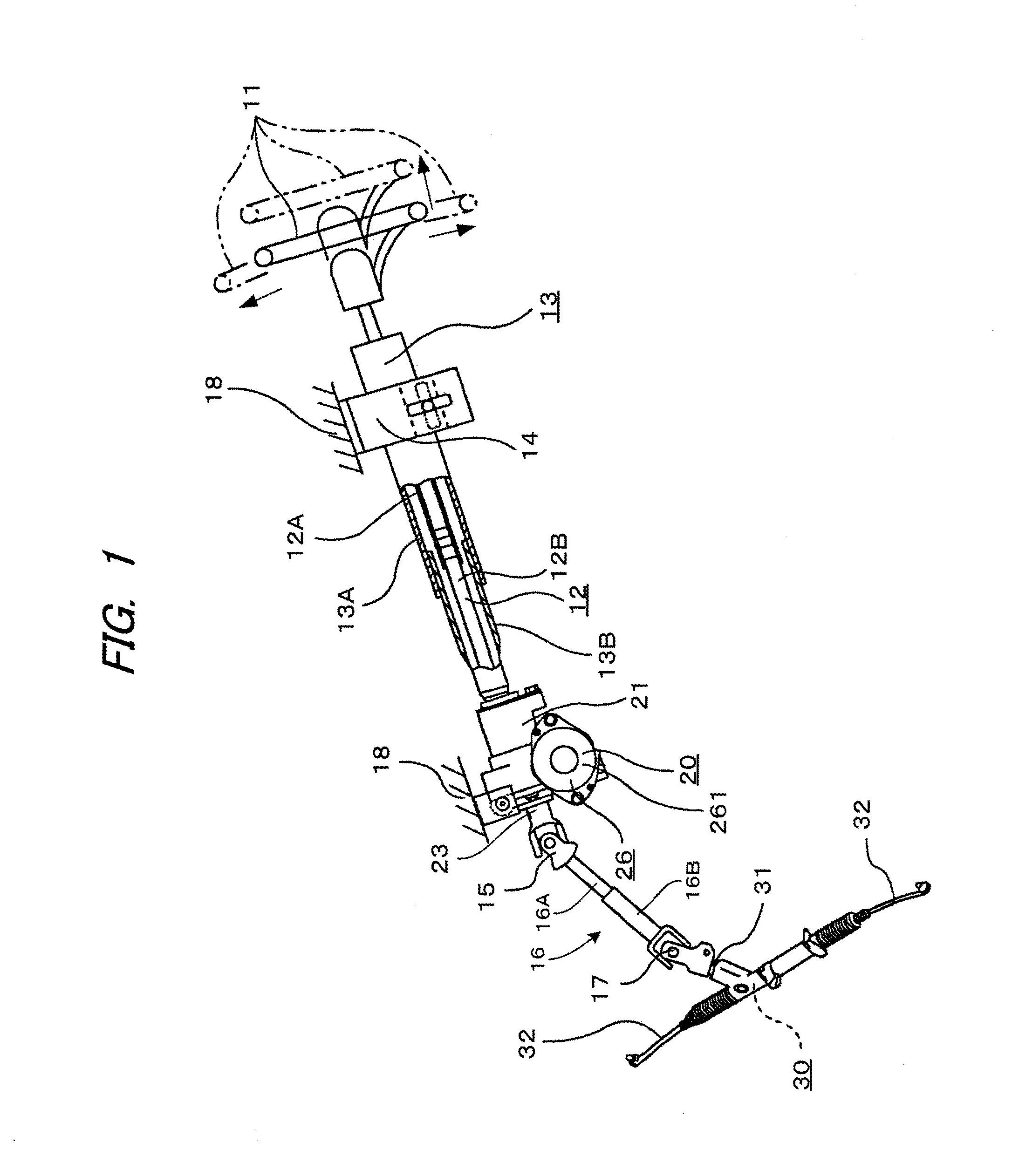
[0030]As shown in FIG. 1, a steering apparatus according to a first embodiment of the present invention includes a steering shaft 12 capable of mounting a steering wheel 11 on the rear side of a vehicle body (on the right side of FIG. 1), a steering column 13 having the steering shaft 12 inserted therein, an assistance device 20 (steering assistance device) for applying auxiliary rotational torque to the steering shaft 12, and a steering gear 30 connected to a portion of the steering shaft 12 on the front side of the vehicle body (on the left side of FIG. 1) through a rack-and-pinion mechanism (not shown).

[0031]The steering shaft 12 includes an outer shaft 12A and an inner shaft 12B. The outer shaft 12A and the inner shaft 12B are interlocked to be able to transmit rotational torque and be capable of relative displacement with respect to an axial direction. In other words,...

second embodiment

[0049]Next, a second embodiment of the present invention will be described with reference to FIG. 6. Hereinafter, features different from those of the above-described first embodiment will be mainly described, and the same features as those of the first embodiment will not be described. The second embodiment is an example in which clearance portions are formed at the tooth roots of the covering portion 61 of the protruding teeth 51.

[0050]As shown in FIG. 6, in a telescopic shaft of the second embodiment, similarly to the first embodiment, the tooth surface 511 of the protruding teeth 51 of the male shaft 16A is covered with the covering portion 61. The tooth surface 611 of the covering portion 61 of the protruding teeth 51 is formed in an arc shape convex toward the outer side of the male shaft 16A in the radial direction. The curvature radius R1 of the tooth surface 611 is smaller than the curvature radius R2 of the tooth surface 411 of the tooth grooves 41. Also, on the tooth top ...


PUM


Abstract

A telescopic shaft includes a male shaft having an outer circumference on which a plurality of protruding teeth are formed, and a female shaft having an inner circumference on which a plurality of tooth grooves are formed. The tooth grooves of the female shaft are fitted onto the protruding teeth of the male shaft such that the male shaft and the female shaft are relatively slidable in an axial direction and such that a rotational torque is transmittable between the male shaft and the female shaft. One of a curvature radius of a tooth surface of the protruding teeth and a curvature radius of a tooth surface of the tooth grooves is smaller than the other of the curvature radius of the tooth surface of the protruding teeth and the curvature radius of the tooth surface of the tooth grooves.

Description

TECHNICAL FIELD [0001]The present invention relates to a telescopic shaft, and particularly, to a telescopic shaft including a male shaft and a female shaft which can transmit rotational torque and are relatively slidable with respect to an axial direction.BACKGROUND ART [0002]A steering apparatus includes telescopic shafts such as an intermediate shaft and a steering shaft, each having a male shaft and a female shaft capable of transmitting rotational torque and connected to be relatively slidable in an axial direction. The intermediate shaft is required to have a telescopic function when joining a universal joint to a pinion shaft to be engaged with a rack shaft of a steering gear so that the intermediate shaft is temporarily compressed before being engaged and joined to the pinion shaft, and also to absorb relative displacement with respect to a vehicle body frame.[0003]The steering shaft transmits a steering force of the steering wheel to vehicle wheels, and is required to have ...

Claims


Application Information

Patent Timeline
IPC IPC(8): F16D3/06
CPCF16D3/06B62D1/16B62D1/20F16C3/035F16C2326/24F16D2001/103
Inventor KUROKAWA, YOSHIFUMI
Owner NSK LTD
Why Eureka
Try Eureka