Heat Recovery System for a Gas Turbine Engine

a gas turbine engine and heat recovery technology, applied in the direction of machines/engines, efficient propulsion technologies, energy-efficient board measures, etc., can solve the problems of engine performance reduction, engine use more fuel, engine work harder to achieve the thrust output selected, etc., to achieve the effect of reducing fuel consumption

Inactive Publication Date: 2014-07-10
FLYSTEAM
View PDF5 Cites 19 Cited by
  • Summary
  • Abstract
  • Description
  • Claims
  • Application Information

AI Technical Summary

Benefits of technology

[0011]According to an embodiment of the present invention, a heat recovery system is disclosed which will reduce fuel consumption in aircraft, watercraft, and any other apparatus which utilizes a gas turbine engine. In a preferred embodiment, heat recovery system is configured to capture

Problems solved by technology

In commercial airplanes, the engine primarily provides thrust, but in addition, it powers many different systems including the pneumatic system, pressurization system, the anti-ice system, and the pressurization of the water and hydraulic system reservoirs The energy needed to run these systems is commonly drawn from the engine's compressor; therefore, the engine must work harder to achieve its selected thrust output.
The dependency of the aircraft systems upon the engine creates additional loads on the engine by increasing rotor speed, exhaust gas temperature, and fuel flow while concurrently reducing engine performance.
Additionally, the engine uses more fuel, produces more noise and CO2 emissions to enable it to power the above systems of the airplane.
The airline passenger feels the e

Method used


Image

  • Heat Recovery System for a Gas Turbine Engine
  • Heat Recovery System for a Gas Turbine Engine
  • Heat Recovery System for a Gas Turbine Engine

Examples


Embodiment Construction

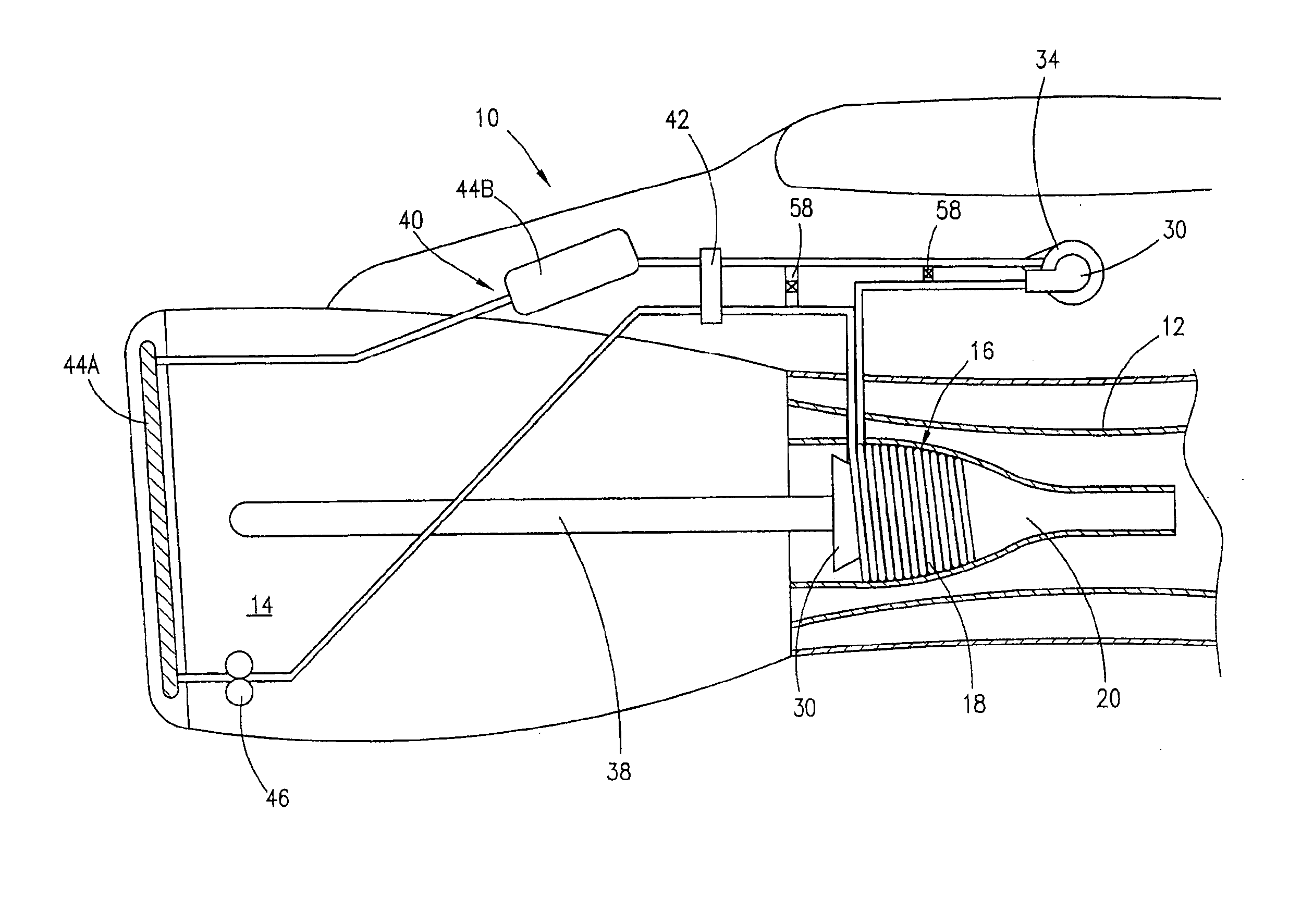
[0021]A heat recovery system 10 utilizing exhaust nozzle 12 of engine 14 is disclosed. Heat recovery system 10 is designed to utilize otherwise wasted energy from exhaust gas which is expelled through exhaust nozzle 12. Heat recovery system 10 can be installed in gas turbine engines for use in aircraft, marine vessels, and any other device having a gas turbine engine.

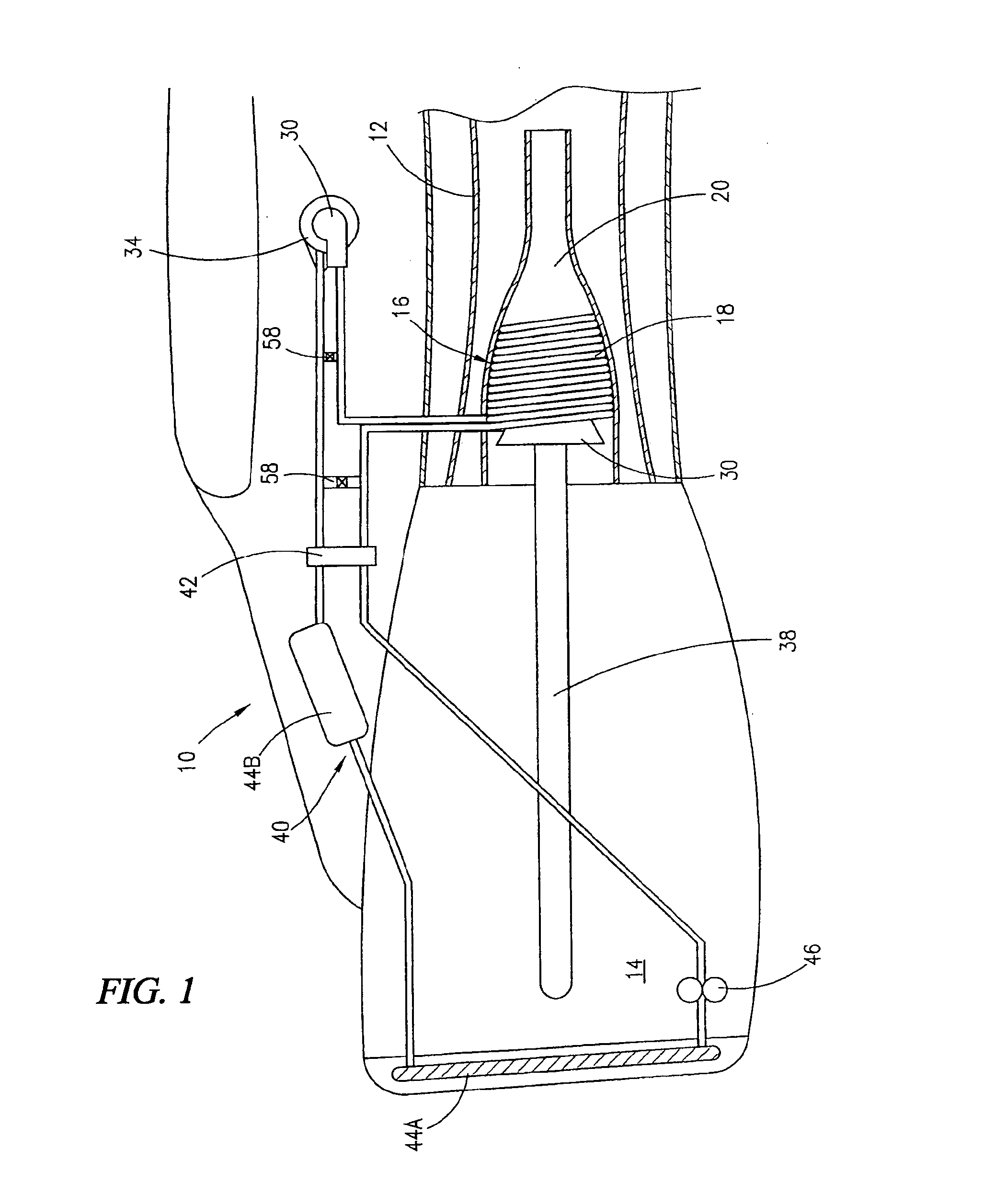
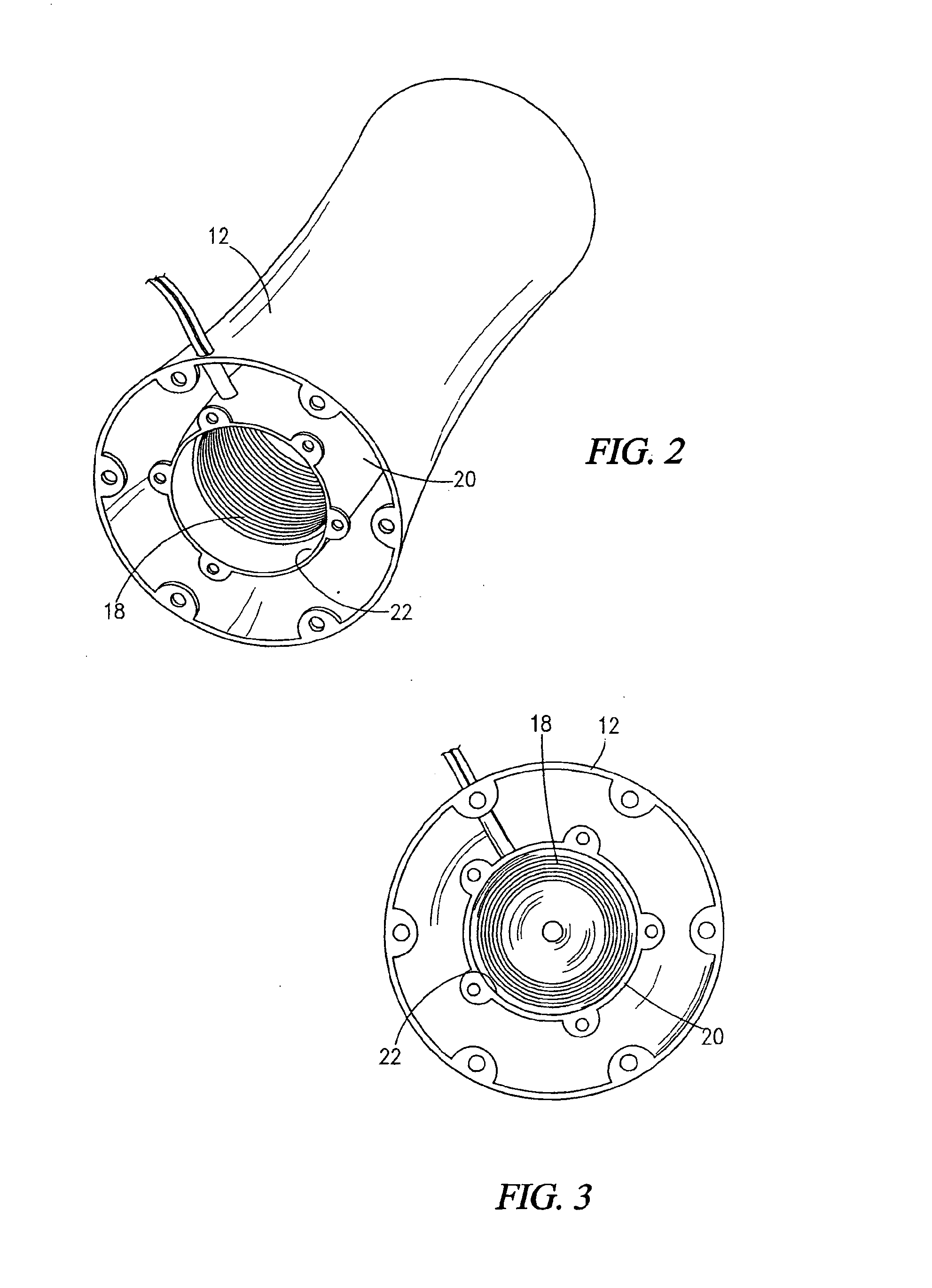
[0022]Engine 14 is equipped with heat recovery system 10 which has a heat exchanger. Heat exchanger 16 can be a substantially hollow coil 18, preferably positioned within centerbody 20. Additionally, coil 18 may adjoin inner surface 22 of the centerbody 20. Coil 18 may have a circular cross section, a substantially rectangular cross section or any other shape which facilitates movement of a fluid 24.

[0023]Alternatively, heat exchanger 16 can be a plurality of jackets 52 positioned between inner skin 48 and outer skin 50 of exhaust nozzle 12. Specifically, jackets 52 can be substantially circumferentially disposed within...


PUM


Abstract

A heat recovery system for an engine having an exhaust nozzle whereby exhaust gas is expelled, the heat recovery system comprising a heat exchanger disposed within the exhaust nozzle, heat exchanger containing a fluid, heat exchanger is further positioned to utilize heat energy from exhaust gas to vaporize fluid a turboexpander fluidly connected to heat exchanger and located downstream from heat exchanger, turboexpander further operatively connected to a utility a condenser fluidly connected to turboexpander and located downstream of turboexpander, and a pump fluidly connected to condenser and located between condenser and heat exchanger, pump is configured to direct fluid from condenser to heat exchanger; whereby operation of engine will generate heat energy in exhaust nozzle, vaporize fluid, and create a pressurized vapor which will drive turboexpander.

Description

PRIORITY CLAIM[0001]This application claims priority to U.S. Non-Provisional patent application Ser. No. 12 / 912,911, filed on Oct. 27, 2010, the entire contents of which are hereby incorporated by referenceTECHNICAL FIELD[0002]This invention relates to a heat recovery system in general, and more particularly, to an improved heat recovery system which utilizes otherwise wasted heat energy in the form of exhaust gas from a gas turbine engine.BACKGROUND ART[0003]An embodiment of the present invention relates generally to a heat recovery system which utilizes wasted heat energy from the exhaust gases of an airplane's gas turbine engine.[0004]In commercial airplanes, the engine primarily provides thrust, but in addition, it powers many different systems including the pneumatic system, pressurization system, the anti-ice system, and the pressurization of the water and hydraulic system reservoirs The energy needed to run these systems is commonly drawn from the engine's compressor; therefo...

Claims


Application Information

Patent Timeline
IPC IPC(8): F02B47/08
CPCF02B47/08B64D13/08B64D15/02F01D15/005F01K23/10F01K25/08F02C6/18F02C7/16F05D2220/32F05D2220/62F05D2220/74Y02T10/12Y02T50/50Y02T50/60
Inventor FONSECA, EDUARDO E.
Owner FLYSTEAM
Why Eureka
Try Eureka