Sonotrode and Anvil Energy Director Grids for Narrow/Complex Ultrasonic Welds of Improved Durability

Inactive Publication Date: 2014-07-10
RINCO ULTRASONICS USA
0 Cites 21 Cited by

AI-Extracted Technical Summary

Problems solved by technology

Use of the piezoelectric transducer reduces the cooling requirements, which result from the generation of the heat, which is a byproduct of the friction.
However, Balamuth does not disclose a complete VFFS or HFFS machine.
When a consumer purchases a bag of chips or other product, a significant percentage of the cost of the purchase is attributable to the packaging.
. . ” Similarly, U.S. Pat. No. 4,161,420 to Clarke for “Ultrasonic Method for Manufacturing Brassiere Ta...

Benefits of technology

[0018]A specially designed sonotrode and anvil are adapted to be used in combination for ultrasonic welding of work pieces, to produce a narrower weld region, but one exhibiting greater durability, thereby permitting use of less packaging material. The contact surfaces comprise a surface of the anvil having a plurality of energy directors, where the plurality of energy directors are arranged into a three-dimensional grid pattern to selectively distribute vibration-transmissive contact into a three-dimensional contact pattern with the sonotrode. The energy directors, which may serve to increase the total surface area of contact between anvil and sonotrode, may comprise a series of plateau surfaces being regularly spaced apart from e...

Abstract

A specially designed sonotrode and anvil are adapted to be used in combination for ultrasonic welding of work pieces, to produce a narrower weld region, but one exhibiting greater durability, thereby permitting use of less packaging material. The contact surfaces comprise a surface of the anvil having a plurality of energy directors, where the plurality of energy directors are arranged into a three-dimensional grid pattern to be capable of distributed vibration-transmissive contact. The energy directors may comprise a series of plateau surfaces being regularly spaced apart from each other in a first direction, and in a second direction that is orthogonal to the first direction, to form the grid pattern. The rectangular-shaped plateaus may be spaced apart by valleys. Engagement of the energy directors of the anvil with the corresponding surface of the sonotrode may cause minor elastic deformation of work pieces positioned therebetween prior to ultrasonic welding.

Application Domain

LaminationLamination apparatus +3

Technology Topic

EngineeringUltrasound +4

Image

  • Sonotrode and Anvil Energy Director Grids for Narrow/Complex Ultrasonic Welds of Improved Durability
  • Sonotrode and Anvil Energy Director Grids for Narrow/Complex Ultrasonic Welds of Improved Durability
  • Sonotrode and Anvil Energy Director Grids for Narrow/Complex Ultrasonic Welds of Improved Durability

Examples

  • Experimental program(2)

Example

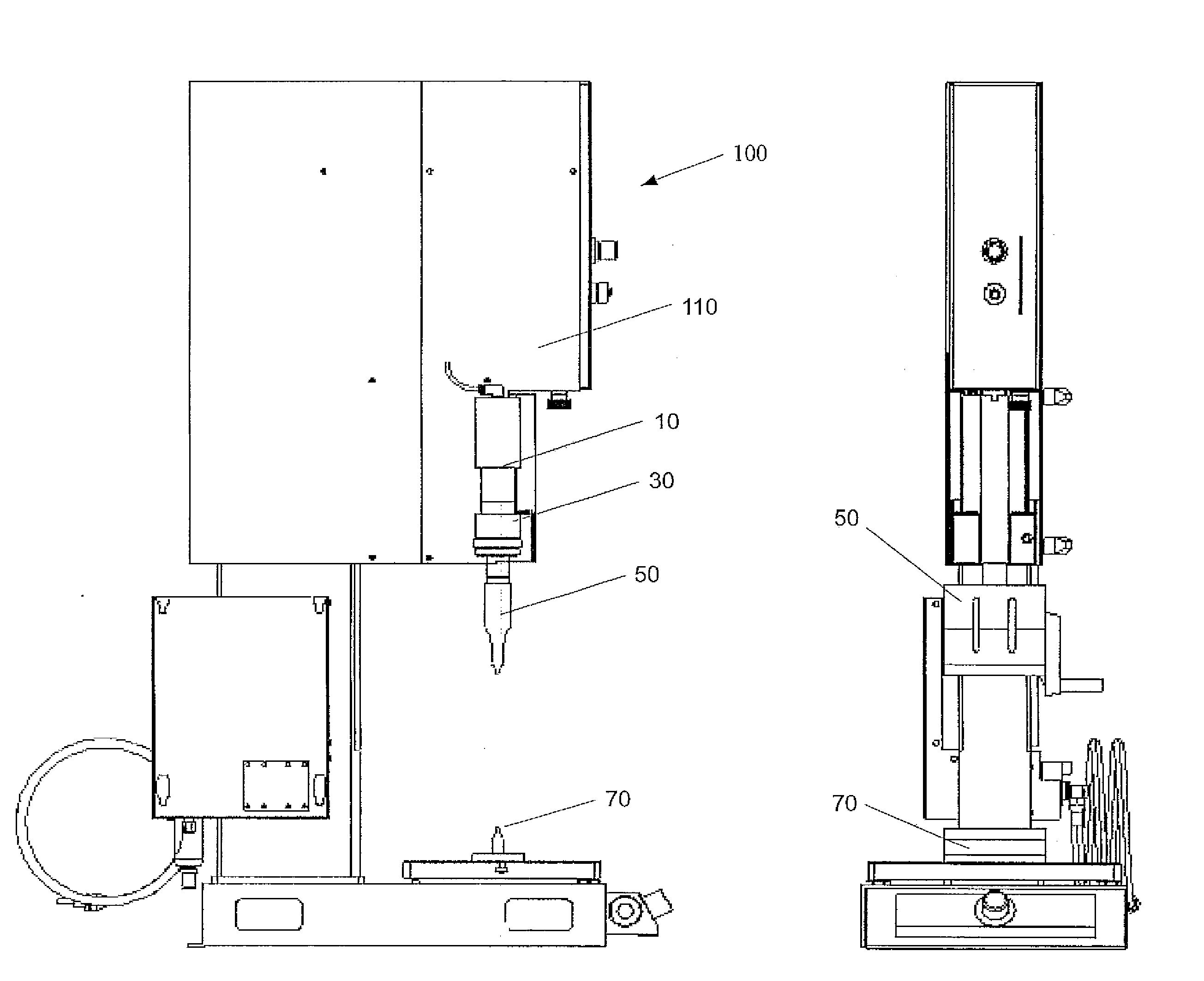
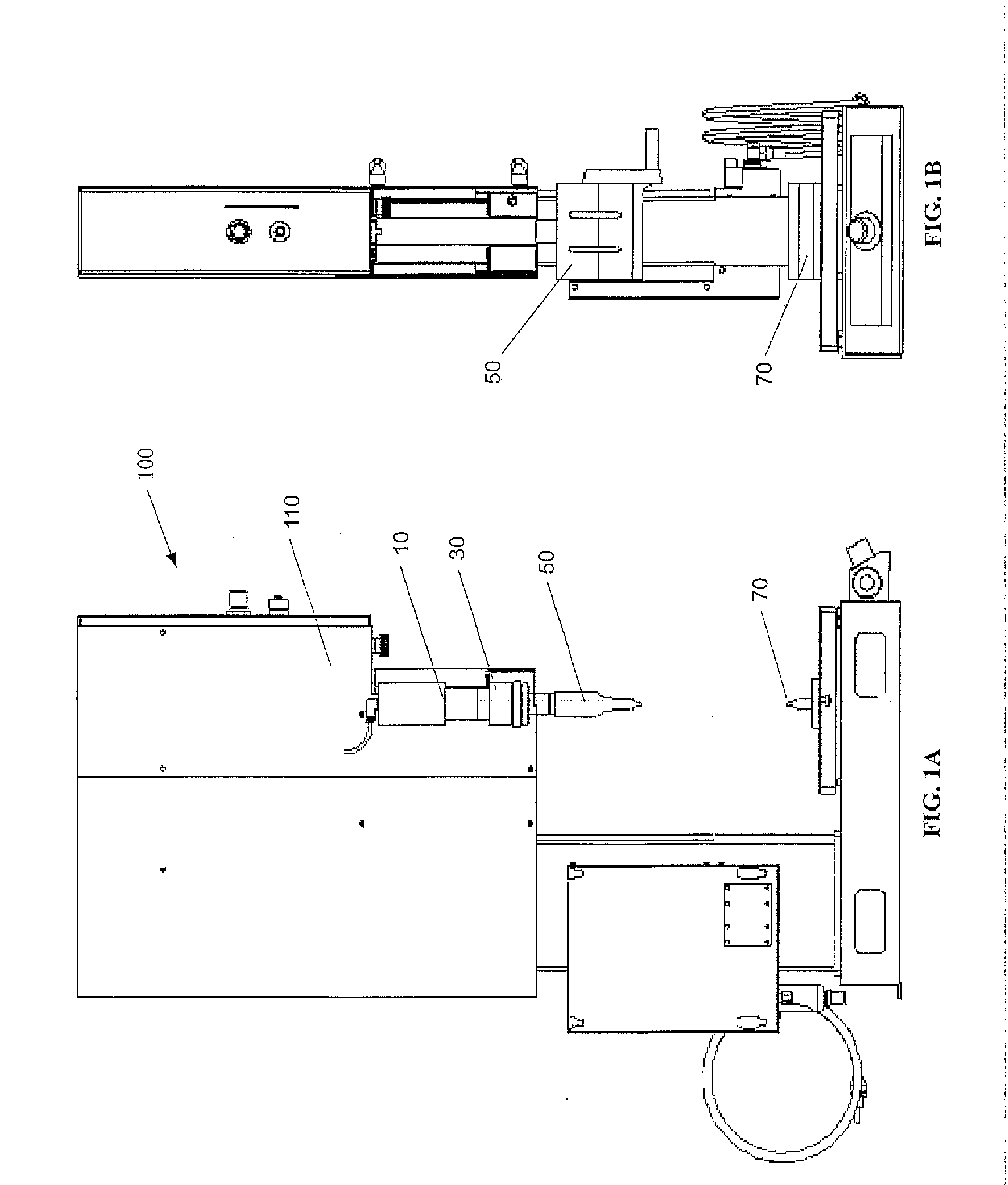
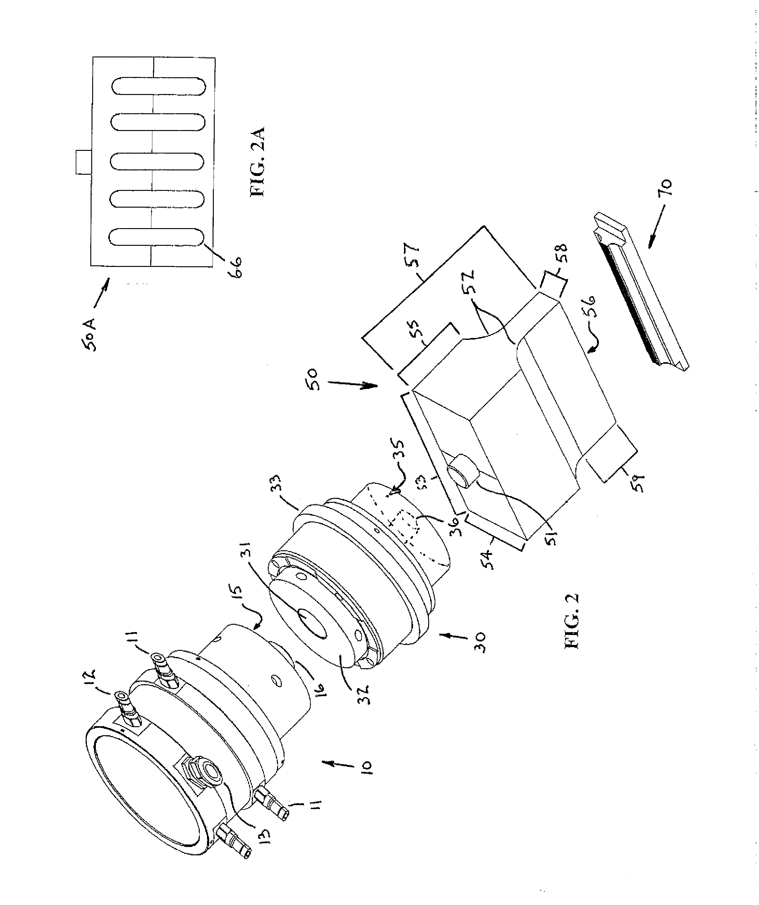
[0058]FIG. 2 shows a first embodiment of the present invention, where the stack includes a converter 10, a booster 30, a sonotrode 50, and an anvil 70 that may be used to weld straight patterns. The converter 10 may be comprised of electrical connectors 11, 12, and 13. The converter 10 may also comprise a flat surface 15 from which protrudes a cylindrical connection means 16 that may be received in a corresponding cylindrical opening 31 in flat surface 32 of booster 30, for attachment of the converter to the booster. The booster 30 may have a flange 33 for use in securing the booster to a press. The booster may have a second flat surface 35 with a cylindrical opening 36 therein, to receive a corresponding cylindrical protrusion 51 of the horn 50. Alternatively, the booster may have a cylindrical protrusion that is received by a cylindrical recess 51A, as seen for the alternative sonotrode 50A of FIG. 10A. The cylindrical protrusion 51 of the horn 50 may protrude from a rectangular block, having a length 53, a width 54, and a depth 55. The rectangular block may transition, at the depth 55, into a narrow rectangular block having a width 58, and being of sufficient length 59, inclusive of the filleted transition areas 52, to create a horn of total length 57. The horn 50 may have a contact surface 56 with a width 58 and length 53 designed for contact with anvil 70.
[0059]The anvil 70, which may be seen in FIGS. 3-9, is configured to be supported in a fixture and be engaged by the surface 56 of sonotrode 50. Anvil 70 may be comprised of a mounting platform 71 having a width 72, length 73, and depth 74. The mounting platform 71 may be used to retain the anvil 70 in the mounting fixture. Protruding away from the mounting platform 71 may be a pedestal portion 75 that shares the same width 72 as the mounting platform, but may have a length 76 that may be shorter than, and be approximately centered upon, the length 73 of the mounting platform 71. The pedestal 75 may narrow, by a pair of radiused surfaces 77, into the engagement surface 78.
[0060]As seen in the enlarged detail of the engagement surface 78 in FIGS. 7 and 8, and the section cut of FIG. 9, the engagement surface 78 of the anvil 70 comprises a specially constructed interface that is designed for receiving the vibrations emitted by the sonotrode 50 to create a narrower ultrasonic weld region which provides greater weld strength than is created by two flat continuous engagement surfaces. The engagement surface 78 comprises a plurality of specially crafted energy directors 79, but are not energy directors in the plain meaning as utilized within the relevant art. An energy director within the prior art is where the work pieces themselves—meaning the parts to be ultrasonically welded—are created such that one part is flat and the other part comes to a sharp point (FIG. 12). In the case of the prior art energy director, with an example being shown by U.S. Pat. No. 6,066,216 to Ruppel, the pointed work piece was to provide a focal point for vibrations to produce frictional heat, and thereby provide a specific volume of melted material to joint the two parts (FIG. 12A). With the invention herein, the anvil and sonotrode may comprise a plurality of specially constructed energy directors 79 that may be arranged into a coordinated three-dimensional grid pattern, being coordinated between the sonotrode and anvil, to thereby selectively increase the total surface area of the anvil that may be capable of distributing vibrations in a three-dimensional contact pattern of vibration-transmissive contact with the sonotrode, and which may also cause a minimal amount of deformation of the work pieces during the initial horn-to-anvil engagement (FIG. 11). The deformation may preferably be limited to a slight amount, and therefore be limited to remain within the elastic range of the material. The increase in surface area of contact may depend upon the width of the plateau surfaces used, as described hereinafter. The three-dimensional contact pattern may be ascertained by reference to FIG. 8, and FIGS. 9 and 10.
[0061]The energy directors 79 of the anvil 70 may be regularly spaced apart from each other, as seen in FIG. 8. The energy directors 79 may preferably be spaced apart in a first direction that may parallel the weld line, and be similarly spaced apart in a second direction away from, or orthogonal to, the weld line to form the grid pattern. In a first embodiment, each of the energy directors 79 may comprise a plateau surface 80 that may be formed by a first angled side surface 81, a second angled side surface 82, a third angled side surface 83, and a fourth angled side surface 84, where the plateau surfaces 80 may comprise a rectangular-shape that may be oriented at a 45 degree angle to the weld line. At the meeting of adjacent side surfaces 81 and 82 of adjacent plateau surfaces 80, there may be a valley bottom or trough line 87 that may be oriented at a minus 45 degree angle with respect to the weld line, and at the meeting of the adjacent side surfaces 83 and 84 of adjacent plateau surface 80, there may be a trough line 88 that may be oriented at a plus 45 degree angle with respect to the weld line.
[0062]The rectangular-shaped plateau surface 80 lends itself very well to two different types of repetitive patterned engagement with the sonotrode described hereinafter; however, other geometric plateau shapes may also be utilized, which would naturally alter the side-surface arrangement. Also, the rectangular-shaped plateau surfaces 80 may each be generally flat, although contoured plateau surfaces 80A may alternatively be utilized, along with a filleted or radiused trough 87A, as seen in FIG. 9A.
[0063]In a first embodiment, seen in FIG. 9, the energy directors 79 of the anvil 70 may have a span therebetween of approximately 0.020 inches, and have a depth from the plateau surface 80 to the troughs 87 or 88 of approximately 0.006 inches. The angled side surfaces may each be at an angle θ, that may be different for various configurations, but in the first embodiment, angled side surfaces 81, 82, 83, and 84 may be oriented such that the angle θ is a 45 degree angle, which, when resolved geometrically, would result in the width of the plateau surfaces 80 being 0.008 inches. Since the dimensions of the energy directors 79 may not necessarily be very large with respect to the material thicknesses being welded, the amount of deformation, discussed earlier, may similarly not be very large, and thus does not pose an issue as to tearing of the material of the work pieces, or even necessarily, issues relating to plastic deformation.
[0064]The sonotrode 50 may have corresponding energy directors, as seen in FIGS. 10A-10E, and may similarly include plateau surfaces 60, as well as side surfaces 61, 62, 63, and 64. The improved sonotrode 50 and anvil 70 may be constructed to have engagement therebetween of energy directors comprising a greater surface area of contact between corresponding plateau surfaces and valleys, than the traditional flat surfaced sonotrode contacting a flat surfaced anvil. This increased surface area of contact, which may be seen from the engagement of the sonotrode and anvil with the work-pieces in FIG. 11 to cause minor elastic deformation prior to application of ultrasonic vibrations, results in more durable ultrasonic welding of two work pieces.
[0065]In one embodiment of welding being accomplished between the sonotrode and anvil of the present invention, alignment of the anvil and sonotrode, which is critical in each case, consists of having the energy director grids aligned so that the plateau surfaces of the sonotrode directly butt against plateau surfaces of the anvil (FIG. 11B). This focuses the vibration energy into a select grid pattern, so that when work pieces are inserted between the sonotrode and anvil (FIG. 11A), ultrasonic welding is achieved more rapidly and efficiently across the entire weld. The butt-surface alignment method is favorably used on thicker work pieces and thinner non-foil applications.

Example

[0066]In a second embodiment of welding according to the present invention, which is advantageous for thinner work pieces, dramatically improved weld durability is achieved by utilizing alignment between the energy director grids whereby the side surfaces of the sonotrode plateaus interlock with the side surfaces of the anvil plateaus (FIG. 11D) in a repeating 3-dimensional pattern, which may include minor elastic deformation of the work pieces. When the work pieces are inserted between the sonotrode and anvil (FIG. 11C), a three-dimensional weld results. The three-dimensional weld exhibits significantly improved durability over that of conventional ultrasonic welds. Depending on the length of the plateau surface utilized on both the anvil and sonotrode, the surface area of contact may be greater or less than the surface area of contact for flat engagement surfaces of the prior art welding machines. Even where the surface area of contact is somewhat less than that of the prior art flat engagement surfaces, increased durability of the weld results. However, where a relatively small plateau surface is used, perhaps being somewhat smaller than the one illustrated in FIGS. 9 and 11D, the surface area of contact would be significantly larger, and may therefore serve to thither reduce the weld times and may also serve to further improve the weld quality/durability. The limiting case would be where the length of the plateau approaches zero, so that there would essentially be interlocking pyramid shapes, and for the sides being at a 45 degree slope, the result would be an increase in surface area of contact of approximately 41.4 percent (The mathematical formula for the surface area of a pyramid being ½×Perimeter×[Side Length]×[Base Area]). Another means of describing and/or visualizing the energy director grids of the present invention, as seen in FIGS. 8-9 and 10E, is as a pyramid frustum.
[0067]Since the alignment of the anvil and sonotrode in the interlocking alignment method is crucial for achieving the results offered herein, the horn 50E may preferably be designed to include a peripheral flange 65 at roughly the mid-plane of the horn. The flange 65 may permit mounting of the horn in closer proximity to the contact surface 56, rather than relying solely upon the mounting connection with the booster, or booster and converter. The need for this type of flanged horn for help with alignment is very pronounced for welding of very thin materials.
[0068]FIG. 13 illustrates the usage of a sonotrode 50B and anvil 70B utilizing the energy directors of the present invention, to create an ultrasonic weld that does not follow a straight-line to create a linear weld in the form of an elongated weld having a rectangular-shaped periphery, and alternatively creates complex, nonlinear weld geometry upon a package to seal the package. FIG. 14 shows anvil 70D, which is capable of being used in the formation of yet another complex curved weld. These non-linear anvil/sonotrode combinations may be utilized to weld materials having a complex irregularly-shaped periphery, rather than the simple linear weld that is typically used, such as for a package of potato chips available at most vending machines. Use of these anvil/horn energy director grid combinations also allows for welding of materials to produce durable 3-dimensional geometries.
[0069]Lastly, FIG. 15 shows an alternative “dual lane” horn 50C, having a first lane 50Ci and a second lane 50Cii. The dual lane horn 50C accomplishes ultrasonic welding according to the present invention, and also accommodates a blade, which may cut through the center of the welded materials along the weld line, after welding is completed, with the blade being able to bottom-out in the valley between the lanes.
[0070]The examples and descriptions provided merely illustrate a preferred embodiment of the present invention. Those skilled in the art and having the benefit of the present disclosure will appreciate that further embodiments may be implemented with various changes within the scope of the present invention. Other modifications, substitutions, omissions and changes may be made in the design, size, materials used or proportions, operating conditions, assembly sequence, or arrangement or positioning of elements and members of the preferred embodiment without departing from the spirit of this invention.

PUM

PropertyMeasurementUnit
Angle45.0°
Surface area
Energy

Description & Claims & Application Information

We can also present the details of the Description, Claims and Application information to help users get a comprehensive understanding of the technical details of the patent, such as background art, summary of invention, brief description of drawings, description of embodiments, and other original content. On the other hand, users can also determine the specific scope of protection of the technology through the list of claims; as well as understand the changes in the life cycle of the technology with the presentation of the patent timeline. Login to view more.

Similar technology patents

MEMS (micro-electro-mechanical system) chip with getters and wafer level packaging method thereof

InactiveCN106115615Aincrease surface areaGuaranteed vacuum
Owner:ANHUI BEIFANG XINDONG LIANKE MICROSYST TECH

Illuminated Brake Assembly and Wheel Well Accessory

InactiveUS20140340917A1great durabilityfacilitate installation
Owner:HARRAGHY DAVID

Gel wrap providing musculo-skeletal support

InactiveUS20060129081A1reduce it effectivenessgreat durability
Owner:GELZONE

Preparation method of drought-resistant water-retaining agent

InactiveCN108559516Aincrease surface areaImprove soil aggregate structure
Owner:裴泽民

Sonotrode and anvil energy director grids for narrow/complex ultrasonic welds of improved durability

InactiveUS20120097339A1great durabilityless packaging material
Owner:RINCO ULTRASONICS USA

Classification and recommendation of technical efficacy words

  • great durability
  • less packaging material

Sonotrode and anvil energy director grids for narrow/complex ultrasonic welds of improved durability

InactiveUS20120097339A1great durabilityless packaging material
Owner:RINCO ULTRASONICS USA

Gel wrap providing musculo-skeletal support

InactiveUS20060129081A1reduce it effectivenessgreat durability
Owner:GELZONE

Illuminated Brake Assembly and Wheel Well Accessory

InactiveUS20140340917A1great durabilityfacilitate installation
Owner:HARRAGHY DAVID

Sonotrode and anvil energy director grids for narrow/complex ultrasonic welds of improved durability

InactiveUS20120097339A1great durabilityless packaging material
Owner:RINCO ULTRASONICS USA
Why Eureka
Try Eureka