Method and system for measuring the resistance of a resistive structure

a resistive structure and resistance technology, applied in the field of electrical arts, can solve the problems of low temperature coefficient, long-term stability, and/or other limitations, and may require sufficiently low manufacturing tolerances of current sense resistors, and methods are unable to compensate for manufacturing tolerances

Active Publication Date: 2014-07-10
ANALOG DEVICES INT UNLTD
View PDF15 Cites 25 Cited by
  • Summary
  • Abstract
  • Description
  • Claims
  • Application Information

AI Technical Summary

Problems solved by technology

For example, such current sense resistors may require sufficiently low manufacturing tolerances, long term stability, a low temperature coefficient, and/or other limitations.
As the specifications become more demanding the component cost and complexity of the system may increase.
For example, the first category of methods is unable to compensate for manufacturing tolerances by simply measuring temperature.
Determining the temperature coefficient(s) of the resistive structure is much more costly.
The test equipment expenditure and the time for determining the temperature change for the stabilization, makes this individual determination of the temperature coefficient (“tempco”) of each resistive structure impractical for most applications.
The foregoing approach regularly leads to poor performance of circuits over temperature.
Another disadvantage of the first category of methods is the inability to detect and compensate for long-term drift of the resistance.
A typical remedy (aside from specifying more costly resistors that have better stability) is regular re-calibration, which typically increases the cost of ownership.
One disadvantage of this category is that the gain factor of the current measurement depends on the DCR of the inductor's coil winding, which (e.g., typically being made of copper), has a tempco in the order of 0.4% per Kelvin, which may be unacceptable for many applications.
Although attempts to provide temperature compensation of the DCR shift by providing means to measure inductor winding temperature (e.g., such as seen in U.S. Pat. No. 7,358,710 to Shiguo et al.,) have been made, they may not be accurate.
For example, in such inductor DCR current sensing approaches, the difficulty in placing the temperature sensor (in this case a negative temperatur...

Method used


Image

  • Method and system for measuring the resistance of a resistive structure
  • Method and system for measuring the resistance of a resistive structure
  • Method and system for measuring the resistance of a resistive structure

Examples


Embodiment Construction

[0028]In the following detailed description, numerous specific details are set forth by way of examples in order to provide a thorough understanding of the relevant teachings. However, it should be apparent that the present teachings may be practiced without such details. In other instances, well-known methods, procedures, components, and / or circuitry have been described at a relatively high-level, without detail, in order to avoid unnecessarily obscuring aspects of the present teachings.

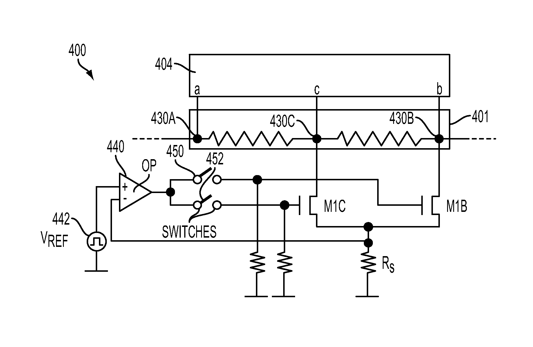
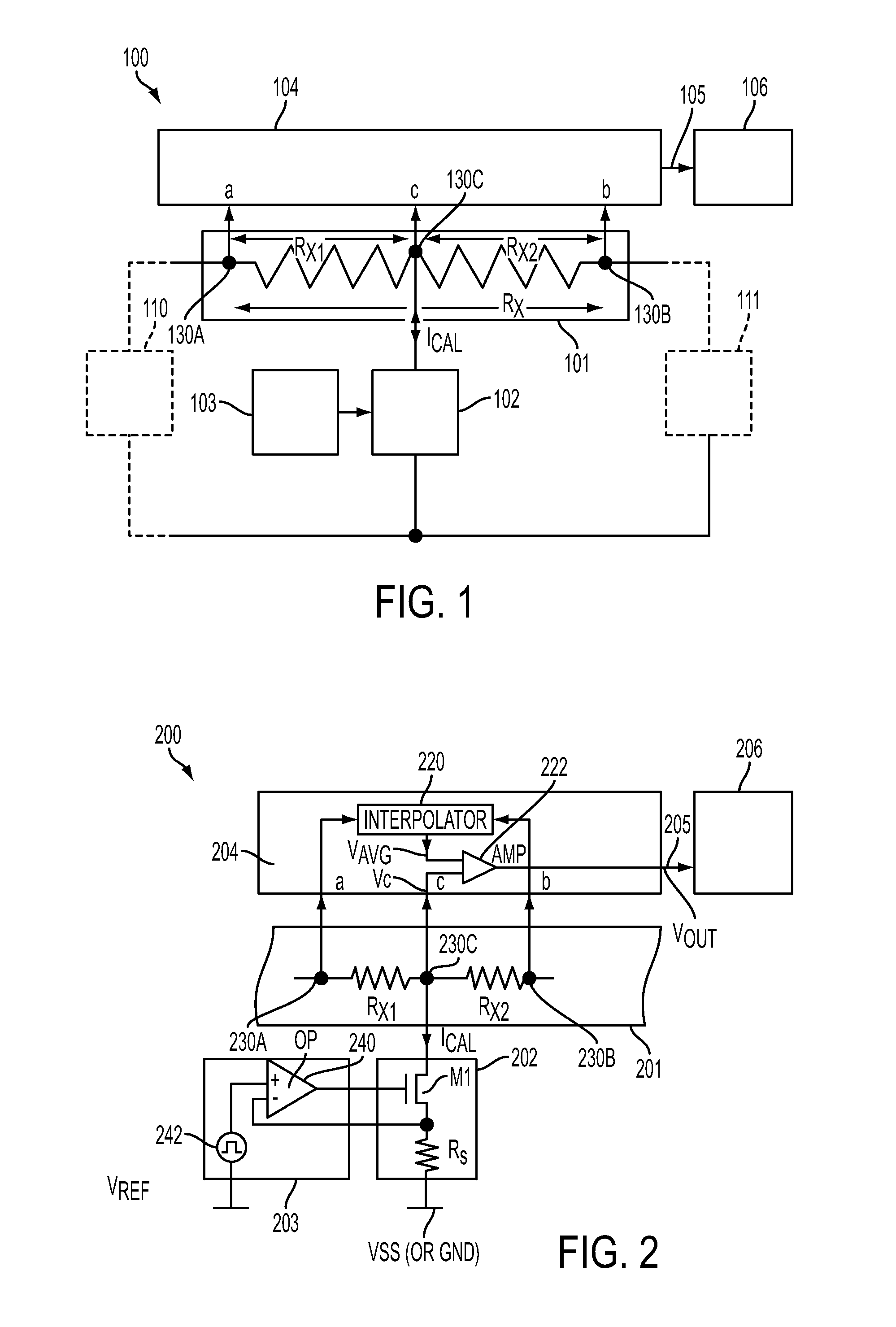
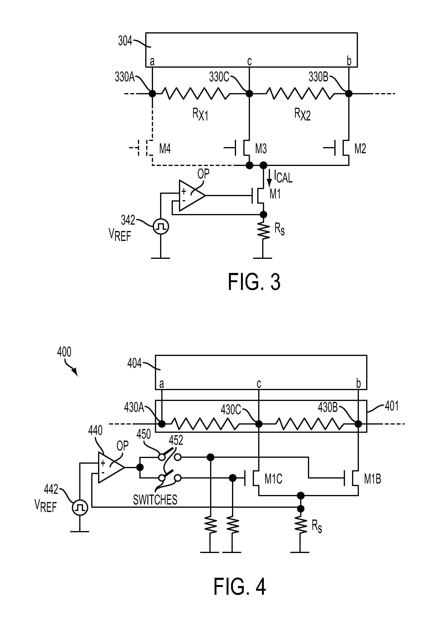
[0029]The various examples discussed below relate to methods and circuits to measure the resistance of a resistive structure during uninterrupted system operation. Suitable resistive structures, among others, are discrete resistors or parasitic resistances associated with the metal layers of integrated circuits, printed circuit board foil, connection wiring, sheet metal, cable runs, or any other resistances, as long as they obey Ohm's law and have sufficiently low parasitic capacitances and inductan...


PUM


Abstract

Method and system for measuring the resistance of a resistive structure having at least three nodes. A first calibration signal is determined by measuring a voltage at an output of the resistance structure when no calibration current is injected into a third node between the first and second nodes of the structure. A calibration current is then injected into the third node and a second calibration signal is determined. The absolute value of the difference between the first calibration signal and the second calibration signal is determined, the absolute value being proportional to a product of the resistance of the resistive structure and the calibration current.

Description

TECHNICAL FIELD[0001]This disclosure generally relates to the electrical arts, and more particularly to calibration of resistive structures.DESCRIPTION OF RELATED ART[0002]In recent years there has been an effort to improve methods and circuits to measure the resistance of resistive structures. Information about the resistance of a resistive structure is useful in many applications, including accurate measurement of current flow. Discrete current sense resistors suitable for accurate output current measurement typically have several requirements. For example, such current sense resistors may require sufficiently low manufacturing tolerances, long term stability, a low temperature coefficient, and / or other limitations. As the specifications become more demanding the component cost and complexity of the system may increase.[0003]Some known approaches accommodate less demanding specifications (and thus lower costs) by providing some form of measurement and / or calibration of a current s...

Claims


Application Information

Patent Timeline
IPC IPC(8): G01R35/00G01R27/14
CPCG01R27/14G01R35/005G01R1/203G01R17/105G01R27/16
Inventor ENGL, BERNHARD HELMUT
Owner ANALOG DEVICES INT UNLTD
Why Eureka
Try Eureka