Masking substrates for application of protective coatings

a technology of protective coating and masking substrate, which is applied in the direction of circuit mask, electrical apparatus construction details, casing/cabinet/drawer, etc., can solve the problems of limiting access, limiting access, and limiting water and other types of moisture protection, so as to achieve a more aesthetically pleasing finish

Active Publication Date: 2014-07-10
HZO INC
View PDF24 Cites 8 Cited by
  • Summary
  • Abstract
  • Description
  • Claims
  • Application Information

AI Technical Summary

Benefits of technology

[0012]When the mask is in place, a protective coating may be applied to the substrate, including each area of the substrate that is protected by a mask. After the protective coating is applied, the protective coating may be cut at a location at or adjacent to the periphery of each mask, and then the protective coating and the underlying mask may be removed from the substrate. If the protective coating is removed at a location just outside of the periphery of the mask, the mask may be removed from the substrate without tearing portions of the protective coating that are to remain in place on the substrate, which may provide the protective coating and, thus, the substrate with a more aesthetically pleasing finish.

Problems solved by technology

The durability of electronic devices is often a concern to consumers, particularly with state-of-the-art portable electronic devices due to their cost and the extent to which consumers typically rely on the electronic devices.
Many protective covers and cases prevent scratches and other physical damage to electronic devices, but protective covers typically provide little, if any protection from water and other types of moisture, and few protective cases protect portable electronic devices from damage that may be caused by water and other types of moisture.
As a result, waterproof cases are often somewhat bulky, or large, and may limit access to certain features of the electronic device and, thus, hinder an individual's ability to use the electronic device in the manner desired by the individual.
Such a protective coating may protect the electronic device even if it is dropped in water, rained on, or otherwise exposed to damaging levels of moisture.
While protective coatings may limit exposure of coated features to water, other types of moisture or contaminants, protective coatings may also adversely affect the performance of some features of an electronic device.
For example, a protective coating may reduce the resolution and clarity of the display and any camera lenses of the electronic device.
A protective coating could also interfere with electrical contacts, such as battery terminals, connector pins, etc.
The protective coating may also negatively impact the performance of certain parts, such as moving parts (e.g., vibration elements, etc.), microphones, speakers, lenses and the like.
In addition, a protective coating could undesirably trap heat within electronic components (e.g., semiconductor device, etc.), decreasing their reliability and the speed with which they operate.

Method used


Image

  • Masking substrates for application of protective coatings
  • Masking substrates for application of protective coatings
  • Masking substrates for application of protective coatings

Examples


Embodiment Construction

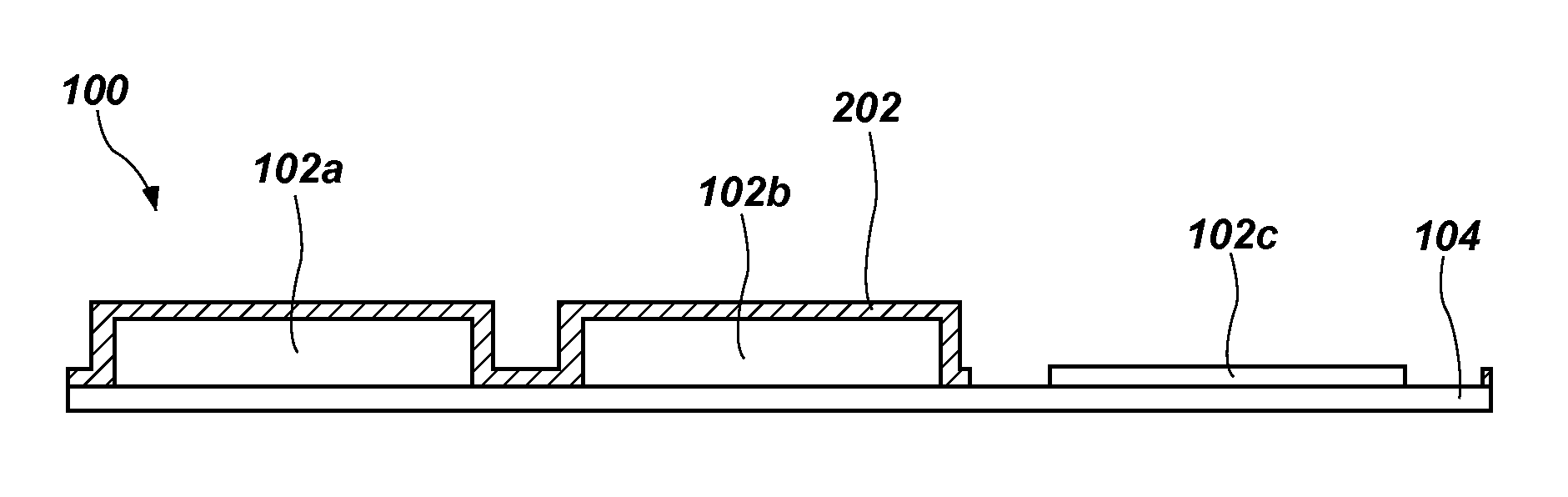
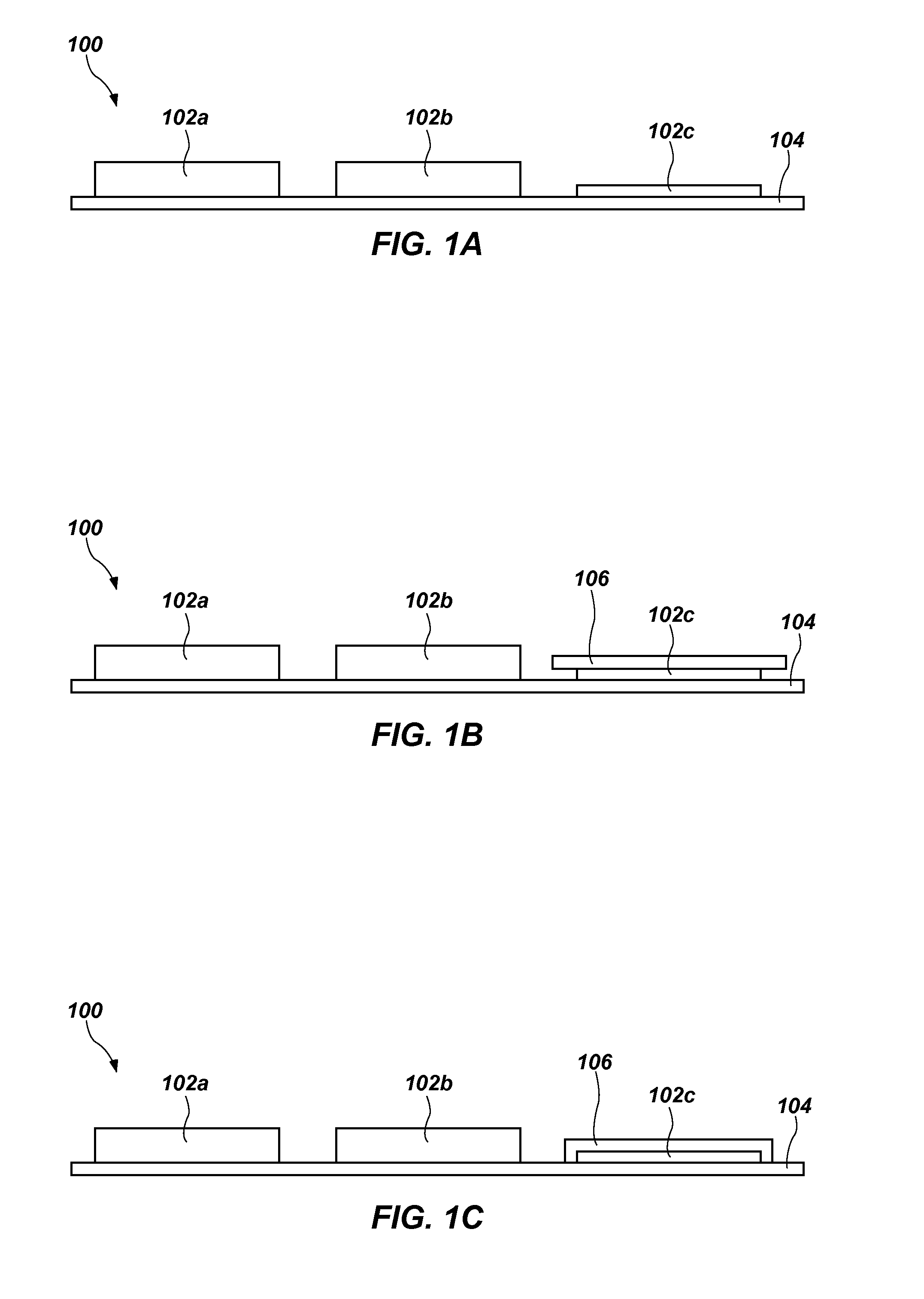
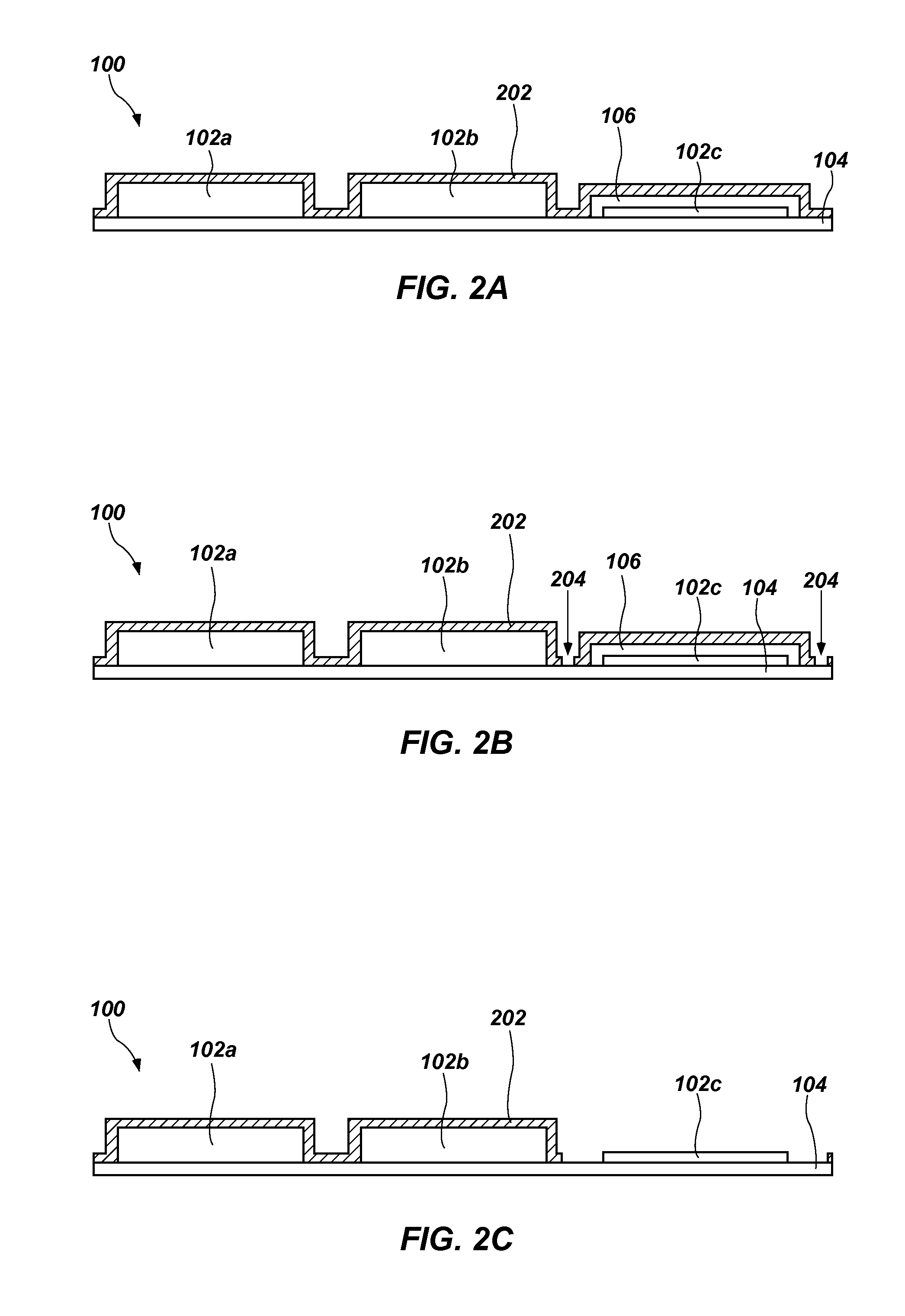
[0022]FIGS. 1A through 1C illustrate an embodiment of a substrate 100. In the depicted embodiment, the substrate 100 comprises a subassembly or an assembly of an electronic device. The substrate 100 may comprise all or part of a portable electronic device, such as a cellular telephone, a tablet computer, a camera, a global positioning system (GPS) receiver, a laptop computer, or any other electronic device. In an embodiment where the substrate 100 comprises a subassembly of an electronic device, it may include a printed circuit board (PCB) or other carrier 104 and one or more components or features 102a-c (e.g., semiconductor devices (e.g., processors, microcontrollers, memory devices, etc.), resistors, capacitors, ports, connectors, electrical contacts, buttons, switches, other components or features, etc.) on the carrier 104. In embodiments where the substrate 100 comprises a subassembly of an electronic device, it may also include other components, such as a display, all or part ...


PUM

PropertyMeasurementUnit
softening pointaaaaaaaaaa
thicknessaaaaaaaaaa
thicknessaaaaaaaaaa

Abstract

A method for applying a protective coating to selected portions of a substrate is disclosed. The method includes applying a mask to or forming a mask on at least one portion of the substrate that is not to be covered with the protective coating. The mask may be selectively formed by applying a flowable material to the substrate. Alternatively, the mask may be formed from a preformed film. With the mask in place, the protective coating may be applied to the substrate and the mask. A portion of the protective coating that overlies the mask may be delineated from other portions of the protective coating; for example, by cutting, weakening or removing material from the protective coating at locations at or adjacent to the perimeter of the mask. The portion of the protective coating that overlies the mask, and the mask, may then be removed from the substrate.

Description

CROSS-REFERENCE TO RELATED APPLICATIONS[0001]This application is a continuation of International Patent Application No. PCT / US2014 / 010526, which was filed pursuant to the Patent Cooperation Treaty on Jan. 7, 2014, titled MASKING SUBSTRATES FOR APPLICATION OF PROTECTIVE COATINGS. The '526 PCT Application claims the benefit of the Jan. 8, 2013, filing dates of U.S. Provisional Patent Application No. 61 / 750,257, titled METHODS FOR REMOVING PROTECTIVE COATING FROM AREAS OF AN ELECTRONIC DEVICE (“the '257 Provisional Application”), and U.S. Provisional Patent Application No. 61 / 750,254, titled METHODS FOR MASKING ELECTRONIC DEVICES FOR APPLICATION OF PROTECTIVE COATINGS AND MASKED ELECTRONIC DEVICES (“the '254 Provisional Application”). The entire disclosure each of the foregoing patent applications is hereby incorporated herein.TECHNICAL FIELD[0002]This disclosure relates generally to methods and systems for applying protective coatings, such as moisture-resistant coatings, to selected ...

Claims


Application Information

Patent Timeline
Patent Type & Authority Applications(United States)
IPC IPC(8): H01L21/64H05K7/02H01L21/67
CPCH01L21/64H05K7/02H01L21/67011H01L21/6715H01L23/3121H01L21/56H01L21/561H05K3/0073H05K3/0079H05K3/284H05K2201/09872H01L2924/0002H01L2924/00C09J2301/304H05K1/181H05K2201/0145B05D1/322C09J9/00
Inventor ASTLE, DAVID JAMESCHILD, TYLER CHRISTENSENKASAGANI, VIMAL KUMARLOOSE, CAMERON LAMARSTEVENS, BLAKE LEROYSORENSON, MAX ERNEST
Owner HZO INC
Why Eureka
Try Eureka