Insertion of medical devices through non-orthogonal and orthogonal trajectories within the cranium and methods of using

a technology of cranial artery and insertion device, which is applied in the field of medical devices, systems and methods for accessing cranial and intracranial structures, can solve the problems of limited brain-machine interface using eeg signals, loss of brain functions, and risk of injury to the intervening healthy brain tissues and blood vessels, so as to enhance the battery life and complexity of each electrode unit, increase the risk of injury, and increase the size

Active Publication Date: 2014-07-10
HUA SHERWIN
View PDF8 Cites 21 Cited by
  • Summary
  • Abstract
  • Description
  • Claims
  • Application Information

AI Technical Summary

Benefits of technology

[0032]The improved method involves modification of implantable devices to specific sizes and shapes so that one or several can be inserted simultaneously through a single entry site in the scalp or cranium by altering the insertion angle of each unit. The individual units are inserted orthogonally and / or nonorthogonally relative to the surface of the scalp or cranium tangent to the singular common entry site. The individual units may be physically connected through a connector head at the common entry site, thereby sharing electronics, power, and other attributes. Additionally, in some embodiments, the distal tip of the shaft and the shaft of the device may be configured so that the devices are insertable directly. By insertable directly it is meant that no or few other tools or instruments are needed to make the entry site and / or the hole through which the implanted device is inserted. For example, the device may be encapsulated in a helical externally threaded screw housing such that the shaft has a sharp distal tip allowing the whole device to pierce through the skin and screw into bone similar to currently used self-drilling cranial plating screws. The self-inserting characteristic enables electrodes to be inserted almost anywhere very quickly in a minimally invasive screw-in or pop-in procedure.
[0047]Another application of the disclosure is the treatment of chronic subdural hematomas. Currently a cranial screw portal is screwed into the skull in a orthogonal manner to apply suction and drain the subdural fluid. However these portals often clog from membranes that develop within the subdural collection. Sometimes a second burrhole has to be drilled in a second site for a loculated collection. Thus the ability to drill and drain through nonorthogonal angles allows wider access to a large subdural collection. Multiple ports also allow irrigation through one port and suction through another in a closed or open circuit system. Traditional burrhole drainage of chronic subdural hematomas typically used two burrholes just for this purpose of irrigation through one and drainage through the second burrhole. This system would also be effective for the more rare subdural empyema or infection of the subdural or epidural space.

Problems solved by technology

In deep brain stimulation, the electrode passes through the cerebral cortex as well as subcortical brain structures to reach the affected deep brain nuclei and therefore risks injury to the intervening healthy brain tissues as well as blood vessels.
These unnecessary yet unavoidable injuries can potentially result in loss of brain functions, stroke, and intracranial hemorrhage.
Although noninvasive, brain-machine interface using EEG signals is currently limited from the significant dampening of the brainwave's amplitude by the cranium and interference by muscles in the scalp and head.
These procedures necessitate a minimum of an overnight stay in the hospital and pose risk to injury of the brain due to the invasiveness of the techniques.
Additionally these “open” techniques pose special challenges for securing the electrode as most technologies require a lead to exit the hole in the skull.
Current techniques for cortical stimulation also risk the development of scarring of the cortex as well as hemorrhage.
Scarring distorts the normal brain architecture and may lead to complications such as seizures.
Additionally, the placement of devices on the surface of the brain poses risks of hemorrhage.
Thus in the case of a deceleration injury like that seen in traffic accidents or falls, the imperfect anchoring of the electrode and the mass of the electrode may cause the electrodes to detach and injure the brain.
Although muscle and other body parts allow the implantation of bion electrodes, the cranium poses a challenge to the bion because the cranium is roughly 1 cm or less in thickness.
However, these patents are not specially adapted for insertion through the skull with multiple components through a single site by means of introducing some components at non-orthogonal angles.
The patent discloses “[t]he microstimulators, of course, may be planted in or near any part of the body, in the brain, a muscle, nerve, organ or other body area” (See 4:24-26) However, no details are provided on how the microstimulators would be or could be implanted into the brain.
Certainly a hypodermic needle cannot be injected through the skull which suggests these stimulators are not designed for such a purpose.
However, neither patent teaches or suggests incorporating the electrode in a screw housing or other component capable of penetrating the skull or cranium (rather than just the skin) for access to the brain's cortex.
However, there is no disclosure of inserting multiple electrodes through the same entry site.
These designs are significantly more invasive than having just one opening in the cranium and continue to carry the risk of electrodes moving with respect to the brain during head injuries.
Placement of electrodes into brain substance increases the risk of injury to brain and blood vessels both during the time of placement as well as afterwards given the physiologic pulsation of the brain in relation to the cranium as well as during episodes of head trauma which causes acceleration and deceleration movement of the brain in relation to the cranium.
Current methods of placement of cortical electrodes necessitates drilling of a burr hole or craniotomy, both of which pose risks to the patient and commonly require a stay in the intensive care unit to monitor postoperatively.
However, if fewer entry sites imply fewer electrodes this may have drawbacks with respect to the variety and intensity of therapy that can be provided.
However this requires frequent EEG conditioning sessions.
However these portals often clog from membranes that develop within the subdural collection.

Method used


Image

  • Insertion of medical devices through non-orthogonal and orthogonal trajectories within the cranium and methods of using
  • Insertion of medical devices through non-orthogonal and orthogonal trajectories within the cranium and methods of using
  • Insertion of medical devices through non-orthogonal and orthogonal trajectories within the cranium and methods of using

Examples


Embodiment Construction

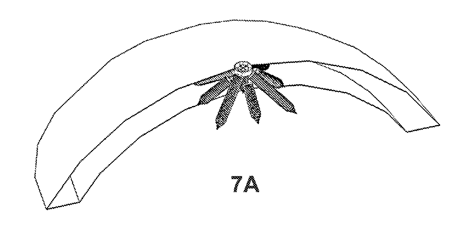
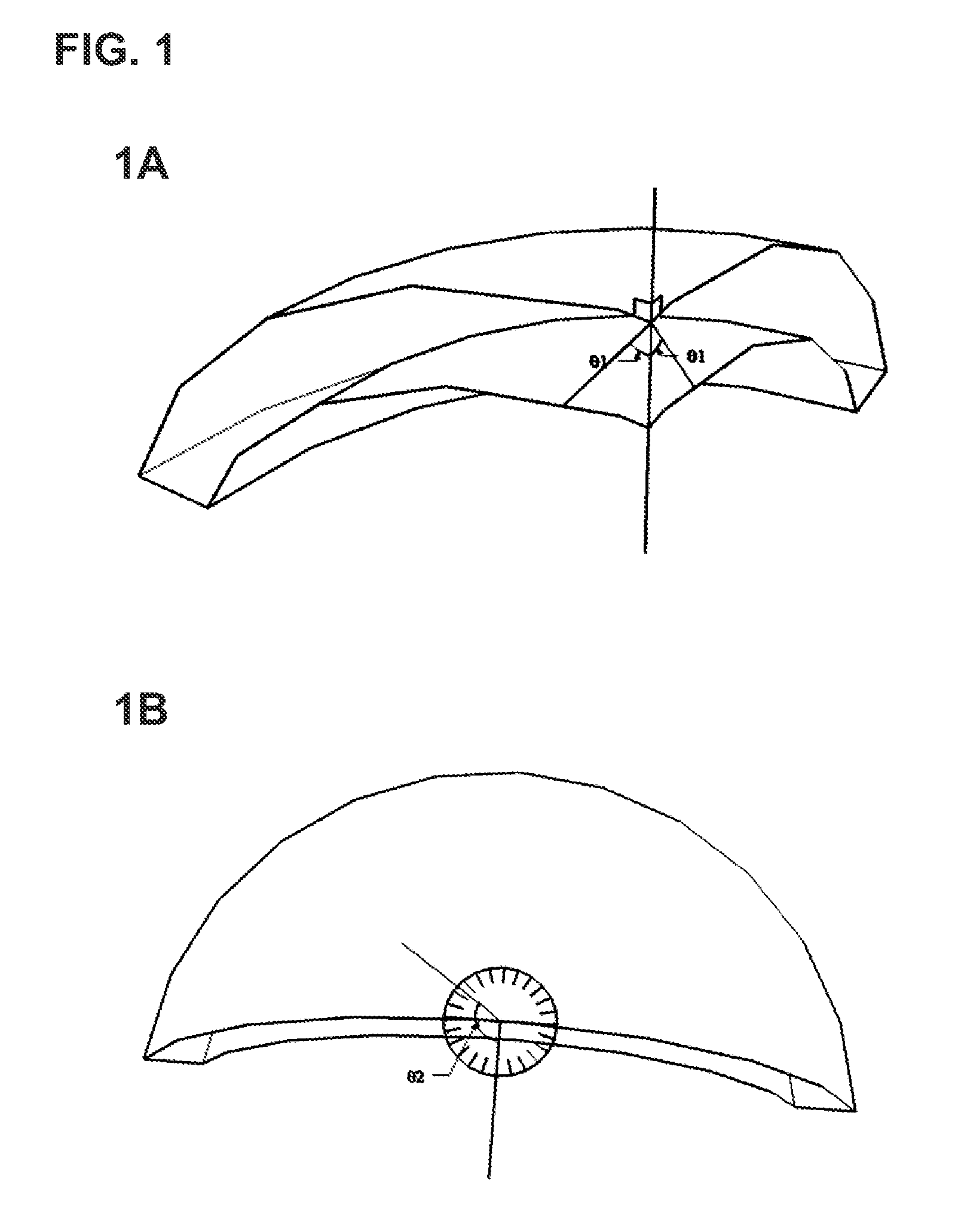
[0062]The present disclosure and method of its use enables multiple effectors, sensors, and other components to fit through a single entry site to provide improved and / or longer-lasting therapeutic benefits. According to some embodiments this is accomplished by inserting the effectors, sensors, other components, or shafts housing any of these elements at different angles to permit greater subsurface reach given a small surface entry site. As used herein, the term “entry site” includes one or more physically distinct openings, holes, or incisions, within close proximity to one another and taking up a relatively small total area of space consistent with minimally invasive surgical procedures. Thus, an “entry site” may be one opening or hole but is not limited to such. The “entry site” may also be an entry zone, area, or region that encompasses two, three, four, or more distinct openings.

[0063]For each entry site, the stimulator / sensor devices may be inserted at several different axial...


PUM


Abstract

An elongated device adapted for insertion, including self-insertion, through the body, especially the skull is disclosed. The device has at least one effector or sensor and is configured to permit implantation of multiple functional components through a single entry site into the skull by directing the components at different angles. The device may be used to provide electrical, magnetic, and other stimulation therapy to a patient's brain. The lengths of the effectors, sensors, and other components may completely traverse skull thickness (at a diagonal angle) to barely protrude through to the brain's cortex. The components may directly contact the brain's cortex, but from there their signals can be directed to targets deeper within the brain. Effector lengths are directly proportional to their battery size and ability to store charge. Therefore, longer angled electrode effectors not limited by skull thickness permit longer-lasting batteries which expand treatment options.

Description

INCORPORATION BY REFERENCE TO ANY PRIORITY APPLICATIONS[0001]The present application claims the benefit of U.S. Provisional Application No. 61 / 789,219, filed Mar. 15, 2013, and is a continuation-in-part of U.S. patent application Ser. No. 13 / 318,462, filed Nov. 1, 2011, which is a U.S. national phase of PCT Application No. PCT / US2010 / 061531, filed Dec. 21, 2010, which claims the benefit of priority of U.S. Provisional Application No. 61 / 288,619, filed Dec. 21, 2009. The contents of each of these applications are hereby incorporated by reference in their entirety.[0002]Any and all applications for which a foreign or domestic priority claim is identified in the Application Data Sheet as filed with the present application are hereby incorporated by reference under 37 CFR 1.57.BACKGROUND[0003]1. Field[0004]The present disclosure relates to medical devices, systems and methods for accessing cranial and intracranial structures. Specifically, the disclosure is directed to altering brain fu...

Claims


Application Information

Patent Timeline
Patent Type & Authority Applications(United States)
IPC IPC(8): A61B5/00A61B5/0478A61B5/0482A61N1/36A61B5/375
CPCA61B5/6865A61N1/0531A61N1/0539A61B5/0478A61N1/36064A61B5/6882A61B5/6868A61B5/4836A61B5/4094A61B5/0482A61N1/36139A61B5/4064A61B5/4076A61B5/375A61B5/291A61N1/05A61N1/372A61B17/1695
Inventor HUA, SHERWIN
Owner HUA SHERWIN
Why Eureka
Try Eureka