Formation property determination apparatus, methods, and systems

a technology of property determination and measurement method, applied in seismology for waterlogging, instruments, borehole/well accessories, etc., can solve the problems of only spot-checking individual depths and computation costs

Active Publication Date: 2014-07-10
HALLIBURTON ENERGY SERVICES INC
View PDF3 Cites 6 Cited by
  • Summary
  • Abstract
  • Description
  • Claims
  • Application Information

AI Technical Summary

Benefits of technology

[0039]Previous solutions to the problem of estimating anisotropy minimize the objective function using a numerical search. The proposed approach uses the eigenvalues derived from a unitary similarity transformation as estimates of the fast and slow principal waves. These estimates can then be used in the objective function as well as the components of equation (2). This makes the objective function more robust, so that it is possible to minimize the objective function analytically.
[0042]Frequency domain embodiments using the aligned eigenvalues have the advantage of directly measuring the angle as a function of frequency. Stress induced anisotropy is detected by a jump of approximately 90° in the angle as a function of frequency, providing a more reliable indicator that is more amenable to automation than conventional methods. Some embodiments shown herein also provide a depth resolution approximately equal to the receiver array length.
[0051]During drilling operations, the drill string 508 (perhaps including the Kelly 516, the drill pipe 518, and the bottom hole assembly 520) may be rotated by the rotary table 410. In addition to, or alternatively, the bottom hole assembly 520 may also be rotated by a motor (e.g., a mud motor) that is located downhole. The drill collars 522 may be used to add weight to the drill bit 526. The drill collars 522 may also operate to stiffen the bottom hole assembly 520, allowing the bottom hole assembly 520 to transfer the added weight to the drill bit 526, and in turn, to assist the drill bit 526 in penetrating the surface 504 and subsurface formations 414.
[0066]Ordering eigenvectors and eigenvalues as described above is relevant to waveforms in the frequency domain. When the waveforms are in the time domain, an embodiment comprises ordering by using the difference in angle across time and receiver ring index. Then fast and slow slowness values can be used as auxiliary parameters and determined by minimizing the objective function.
[0088]Using the apparatus, systems, and methods disclosed herein, those in the petroleum recovery industry and other industries may now be able to more accurately and rapidly assess the properties of geologic formations, including stress induced anisotropy. Increased operational efficiency and client satisfaction may result.

Problems solved by technology

However, using the embodiments described herein it is also possible, using the eigenvalues, to solve for the angles as a function of frequency analytically—without recourse to numerical search methods, which are not guaranteed to find the global minimum, and can be computationally expensive.
Visual inspection by the operator of two very similar and sometimes noisy dispersion curves can be impractical for processing an entire well bore log, so that individual depths are only spot-checked.

Method used


Image

  • Formation property determination apparatus, methods, and systems
  • Formation property determination apparatus, methods, and systems
  • Formation property determination apparatus, methods, and systems

Examples


Embodiment Construction

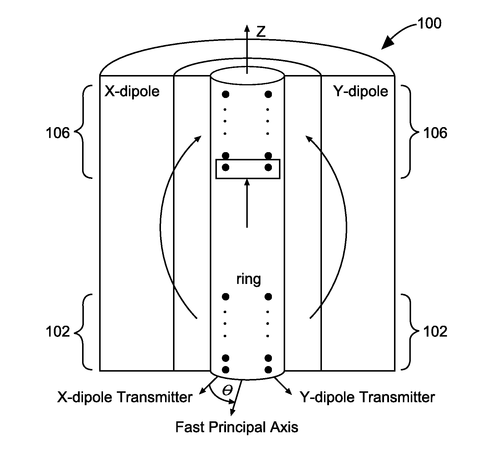
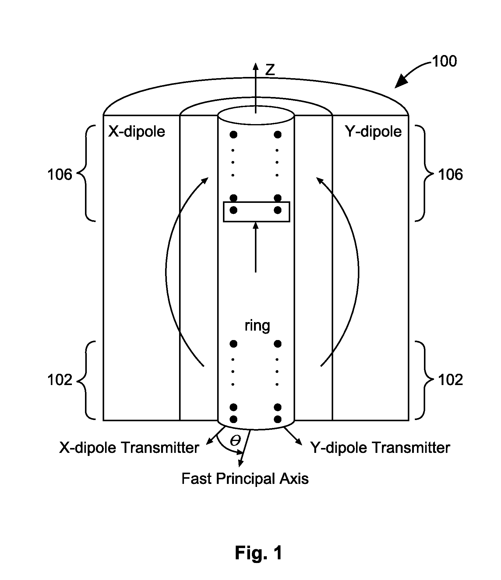
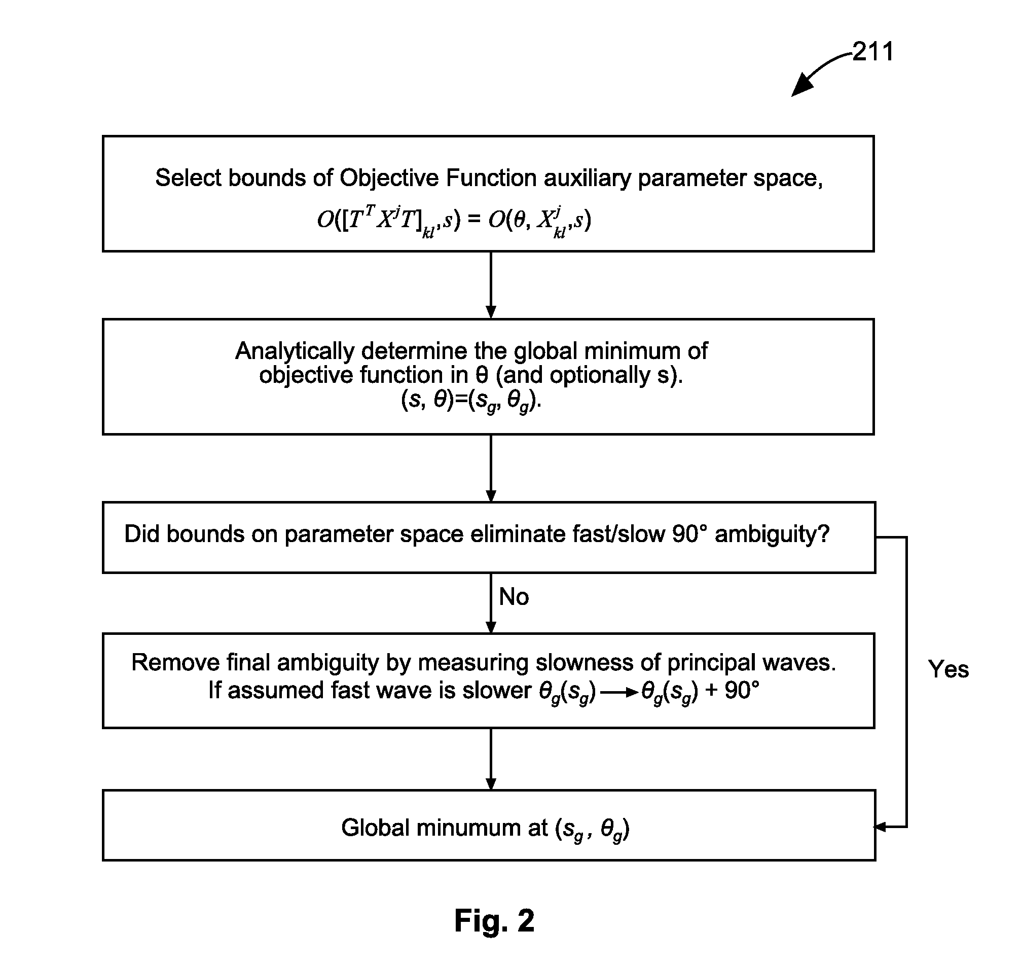
[0013]Algorithms for anisotropy processing of cross-dipole acoustic waveforms can operate to minimize an objective function whose parameters are the azimuth angle, θ, of the X-dipole transmitter relative to the fast principal flexural wave axis and a set of auxiliary parameters. The auxiliary parameters are used to characterize the received waveforms as functions of slowness, borehole radius, etc. Minimizing the objective function with respect to all the parameters can provide a desired anisotropy angle. The dependence of the objective function on angle is based on the assumption that the cross-dipole acoustic waveforms obey the Alford rotation equations, i.e. the 2×2 cross-dipole waveform matrix, Xkl, can be diagonalized by a similarity transformation, TT(θ)XT(θ), using a real 2×2 orthonormal matrix, T(θ). The objective function measures how well this is accomplished, for example, by minimizing the off-diagonal elements of the similarity transformation with respect to angle.

[0014]E...


PUM


Abstract

In some embodiments, apparatus and systems, as well as methods, may operate to record a plurality of acoustic waveforms comprising cross-dipole waveforms and corresponding to acoustic waves received 5 at azimuthally orthogonal dipole receiver arrays surrounded by a geological formation, the waves being generated by azimuthally orthogonal dipole transmitter arrays. Further activity may include defining an objective function dependent on the cross-dipole waveforms, eigenvalues, an azimuth angle corresponding to an 10 orientation of the transmitter and receiver arrays; minimizing the objective function with respect to said angle and the set of auxiliary parameters; and determining at least one property of the geological formation based on the global minimum. Additional apparatus, systems, and methods are disclosed.

Description

RELATED APPLICATION[0001]This international application claims priority benefit to U.S. Provisional Patent Application Ser. No. 61 / 533,620, filed Sep. 12, 2011, and to U.S. Provisional Patent Application Ser. No. 61 / 533,420, filed Sep. 12, 2011, each of which is incorporated herein by reference in its entirety.BACKGROUND[0002]Conventional algorithms use only numerical searching for anisotropy processing of cross-dipole acoustic waveforms, to minimize an objective function whose parameters are the azimuth angle of the X-dipole transmitter relative to the fast principal flexural wave axis, and a set of auxiliary parameters. The auxiliary parameters are used to characterize the received waveforms as functions of slowness and borehole radius, among others. Sometimes the processing is used to determine the location and amount of stress-induced anisotropy in a geological formation.BRIEF DESCRIPTION OF THE DRAWINGS[0003]FIG. 1 is an acoustic tool operating according the various embodiments...

Claims


Application Information

Patent Timeline
Patent Type & Authority Applications(United States)
IPC IPC(8): E21B49/00G01V1/40
CPCG01V1/50E21B49/00G01V1/40G01V1/36G01V2210/1299G01V2210/27G01V2210/67
Inventor COLLINS, MARK V.CHENG, ARTHUR
Owner HALLIBURTON ENERGY SERVICES INC
Why Eureka
Try Eureka