
Methods for reducing raw particulate engine emissions

a technology of raw particulate and engine, applied in the direction of machines/engines, electric control, combustion engines, etc., can solve the problems of increasing pressure loss, method of load control, and reducing the efficiency of combustion engines, so as to reduce fuel consumption and efficiency, increase the overall engine efficiency, and reduce fuel consumption. the effect of consumption

Active Publication Date: 2014-07-17
FORD GLOBAL TECH LLC
View PDF2 Cites 7 Cited by
  • Summary
  • Abstract
  • Description
  • Claims
  • Application Information

AI Technical Summary

Benefits of technology

The patent describes a method for starting an engine from rest with reduced emissions of particulate matter. The method involves injecting fuel into the engine at a minimum pressure, adjusting the air-fuel ratio, and spark-igniting the fuel in a stratified mixture. The high injection pressure allows for better mixing of the fuel with the oil and reduces the amount of fuel that reaches the cylinder walls during injection. This reduces wear and tear on the engine and minimizes the formation of precipitates during the starting phase.

Problems solved by technology

However, operating methods within a spark-ignition or applied-ignition engine render fuel consumption and efficiency problematic.
In particular, closing of the throttle valve increases a pressure loss induced in the air across the throttle valve, which produces a lower induced air pressure downstream of the throttle valve and ahead of a cylinder inlet.
This method of load control, however, also has disadvantages, especially in the part load range, wherein low loads may require a high degree of throttling.
However, the high degree of throttling may occur via a pressure reduction in the intake section, which results in exhaust and refill losses that rise with a decreasing loads.
Further, the time available for injecting fuel, preparing the mixture in the combustion chamber, namely the intermingling of air and fuel to a sufficiently desired extent, and preparing the fuel in the context of preliminary reactions, including vaporization, and ignition of the prepared mixture is comparatively short, and may be, for example, on the order of milliseconds.
However, a disadvantage is that the excessive amount of fuel also leads to very high raw particulate emissions during the starting phase.
Therefore, filter regenerations may occur infrequently when the engine is operated for short periods of time.
Frequent cold starts by the engine and / or short journey lengths / durations may further lead to high raw particulate emissions.
Thereby, frequent regeneration of the particulate filter may become necessary, however, at the same time, the basic boundary conditions for regeneration of the particulate filter, in particular high temperatures, are not achieved.
In the case of internal combustion engines operated with excess air, e.g., direct-injection spark-ignition engines or lean-burn spark-ignition engines, reducing the nitrogen oxides NOx in the exhaust gas is not possible, owing to the principle involved, that is to say owing to the absence of a reducing agent.
In this way, the methods ensure that the fuel injected, which may be substantially reduced in some cases, evaporates in the combustion chamber while also preventing a combustion wall wetting due to the high levels of fuel overfueling, which leads to high particulate emissions.
Therefore, it is not only that a portion of fuel may enter the crank case together with the oil and blow by gas for contribution to oil dilution, but that the fuel on the combustion chamber walls, which are cold during starting, contributes greatly to increased raw particulate emissions.

Method used


Image

  • Methods for reducing raw particulate engine emissions
  • Methods for reducing raw particulate engine emissions
  • Methods for reducing raw particulate engine emissions

Examples


Embodiment Construction

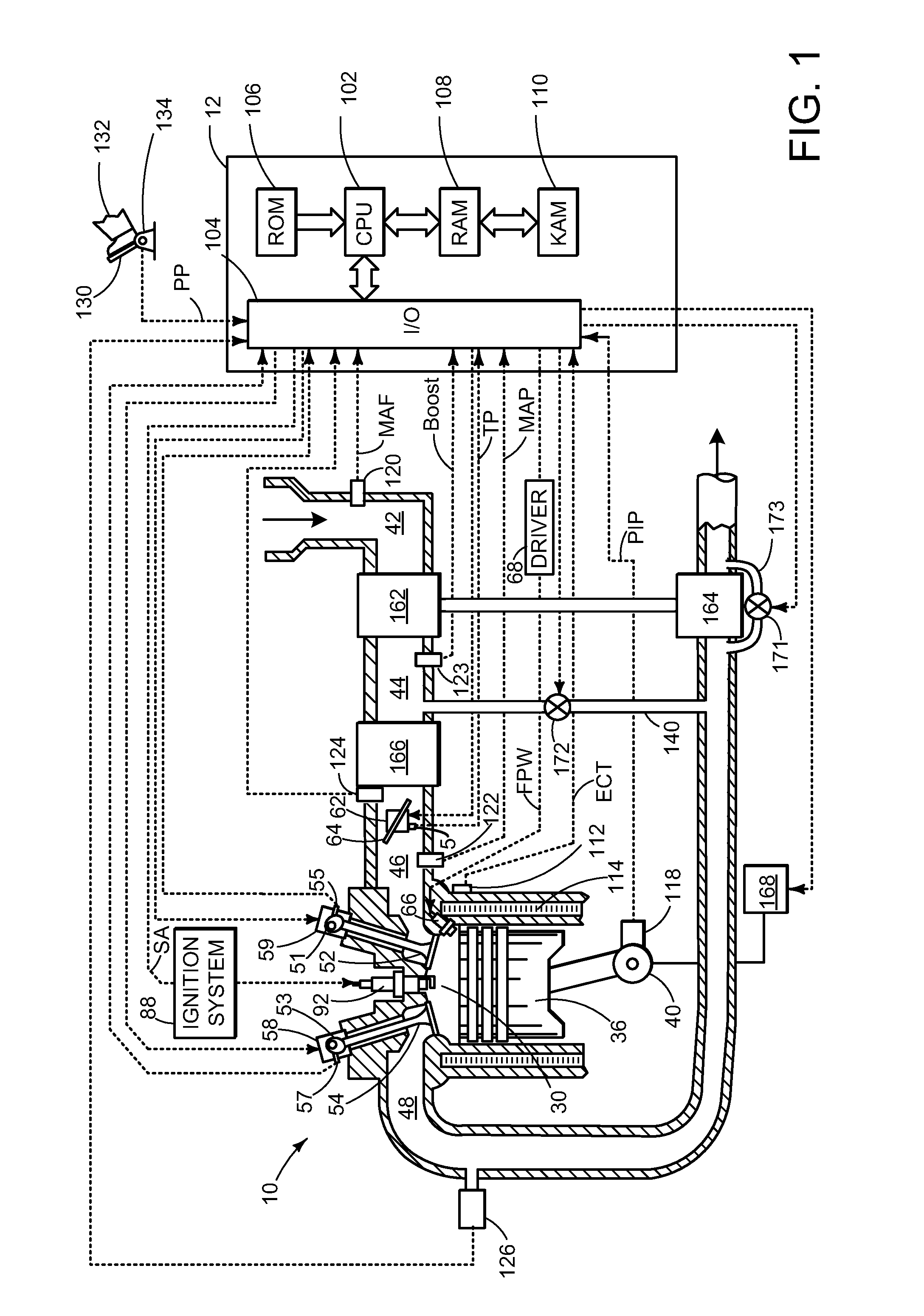
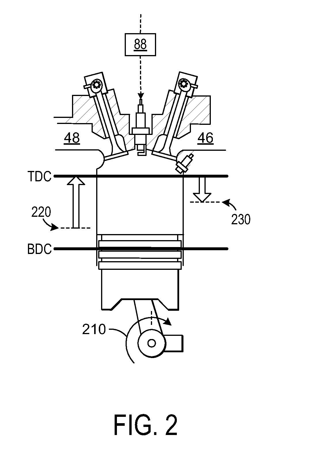
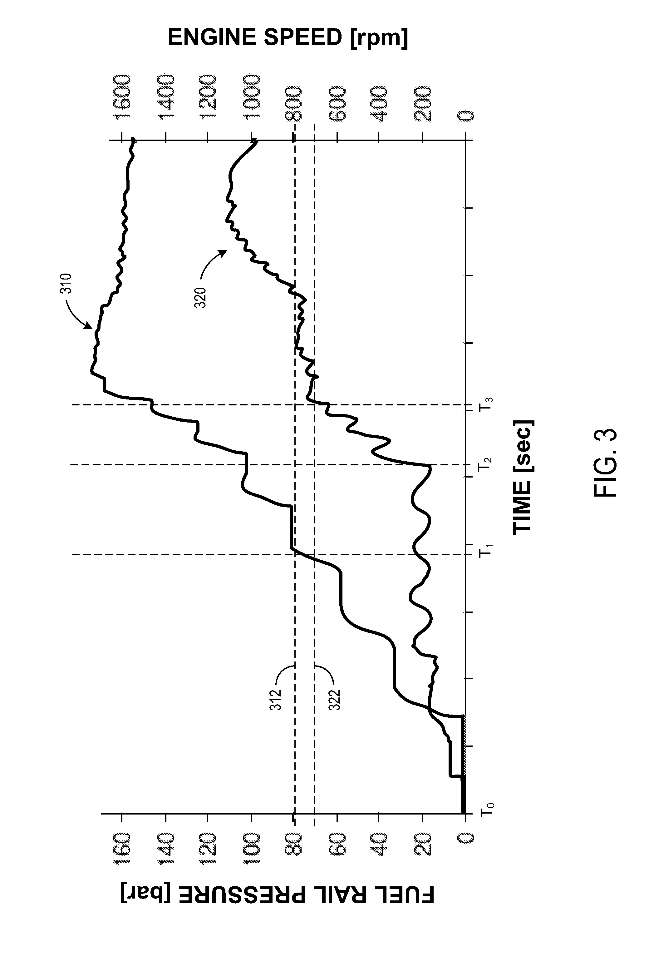
[0025]The methods described may reduce raw particulate emissions from an applied-ignition internal combustion engine. As such, FIGS. 1-2 shows an example engine diagram in which a piston connected to a crankshaft oscillates between a BDC position and a TDC position during engine operation, and in which an injection nozzle is provided for directly injecting the fuel. Then, FIGS. 3-4 illustrate the relationship of various engine parameters to engine start duration, which may be reduced relative to a time threshold using the methods described. FIG. 5 further illustrates how a controller may make one or more adjustments during the starting phase based on the engine conditions at engine start-up. FIG. 6 illustrates an example flow chart of the method according to the present disclosure, while FIGS. 7-8 provide graphical illustrations of the engine start and crank operations to provide an alternate illustration of the methods described herein.

[0026]Referring now to FIG. 1, internal combus...


PUM


Abstract

The methods described allow for reducing particulate emissions from a direction injection engine during a starting phase, while also maintaining the engine start phase within a predetermined threshold. In one particular example, the methods comprise adjusting at least one of a fuel release pressure threshold and enrichment factor based on an engine condition; activating a starting device to rotate a crankshaft coupled to an engine cylinder without injecting any fuel; supplying fuel to the cylinder based on the enrichment factor only when a fuel pressure exceeds the fuel release pressure threshold; and stratifying a cylinder charge while adjusting a fuel injection within a compression phase and / or expansion phase of the engine. In this way, an amount of fuel injected may be evaporated in the combustion chamber while preventing a combustion wall wetting, which allows for reduced particulate emissions, particularly at reduced temperatures.

Description

CROSS REFERENCE TO RELATED APPLICATIONS[0001]The present application claims priority to German Patent Application No. 102013200331.5, filed on Jan. 11, 2013, the entire contents of which are hereby incorporated by reference for all purposes.FIELD[0002]The present description relates to a method for reducing raw particulate emissions from a direct injection engine.BACKGROUND AND SUMMARY[0003]A fundamental aim of internal combustion engines is to minimize fuel consumption while increasing the overall engine efficiency. However, operating methods within a spark-ignition or applied-ignition engine render fuel consumption and efficiency problematic. For example, a conventional spark-ignition engine with intake manifold injection, also referred to as port fuel injection, operates with a homogeneous fuel / air mixture that is prepared by an external mixture formation by introducing the fuel into the air within the air intake manifold. Furthermore, load control is accomplished by means of a t...

Claims


Application Information

Patent Timeline
Patent Type & Authority Applications(United States)
IPC IPC(8): F02B17/00
CPCF02B17/005F02D41/062F02D41/064F02D41/065F02D41/3023F02D41/3076F02D41/401F02D41/402F02D2200/0602
Inventor RUHLAND, HELMUT HANSLOUVEN, GEORG
Owner FORD GLOBAL TECH LLC
Learn More