Hydrogen station

a hydrogen station and hydrogen technology, applied in the field of hydrogen stations, can solve the problems of large expansion of facilities, inability to perform uniform temperature control in hydrogen stations, and inability to meet the needs of customers, and achieve the effect of suppressing an increase in the internal temperature of hydrogen tanks and easy controlling hydrogen temperatur

Active Publication Date: 2014-07-17
KOBE STEEL LTD
View PDF3 Cites 47 Cited by
  • Summary
  • Abstract
  • Description
  • Claims
  • Application Information

AI Technical Summary

Benefits of technology

[0016]An object of the present invention is to provide a hydrogen station including a reciprocating compressor and capable of easily controlling a temperature of hydrogen supplied thereto and suppressing an increase in an internal temperature of a hydrogen tank when hydrogen is charged to the hydrogen tank.

Problems solved by technology

However, since the flow rate is gradually adjusted in any method of the “suction valve unloading method” and the “clearance pocket method”, it is difficult to perform a uniform temperature control in the hydrogen station.
Furthermore, as the “suction valve unloading method”, a method is proposed which continuously adjusts the capacity in the range of about 20 to 100% by combining a hydraulic control with a suction valve unloading mechanism, but this method is not practical in that a facility greatly increases in size.

Method used


Image

  • Hydrogen station
  • Hydrogen station
  • Hydrogen station

Examples


first embodiment

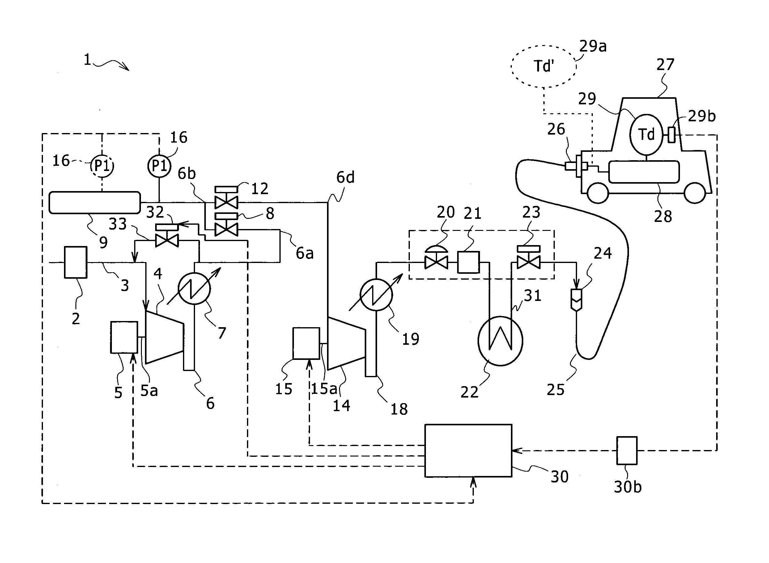
[0027]FIG. 1 illustrates a configuration of a hydrogen station 1 according to a first embodiment of the present invention. The hydrogen station 1 has a configuration in which hydrogen (a hydrogen gas) is first supplied from a hydrogen supply source (not shown) to a low-pressure-stage reciprocating compressor (a low-pressure-side reciprocating compressor: a first compressor) 4 through a supply passage 3 equipped with a filter 2.

[0028]A driver 5 (a motor or the like) is connected to the low-pressure-side reciprocating compressor 4 through a drive shaft 5a. The low-pressure-side reciprocating compressor 4 is driven by the rotation of the drive shaft 5a of the driver 5. The driver 5 is a motor which is driven by an inverter. The revolution of the driver 5 is controllable. That is, the drive shaft 5a may be rotated at an arbitrary revolution. Furthermore, the driver 5 may be any machine of which the revolution is controllable, and is not limited to the motor which is driven by the invert...

second embodiment

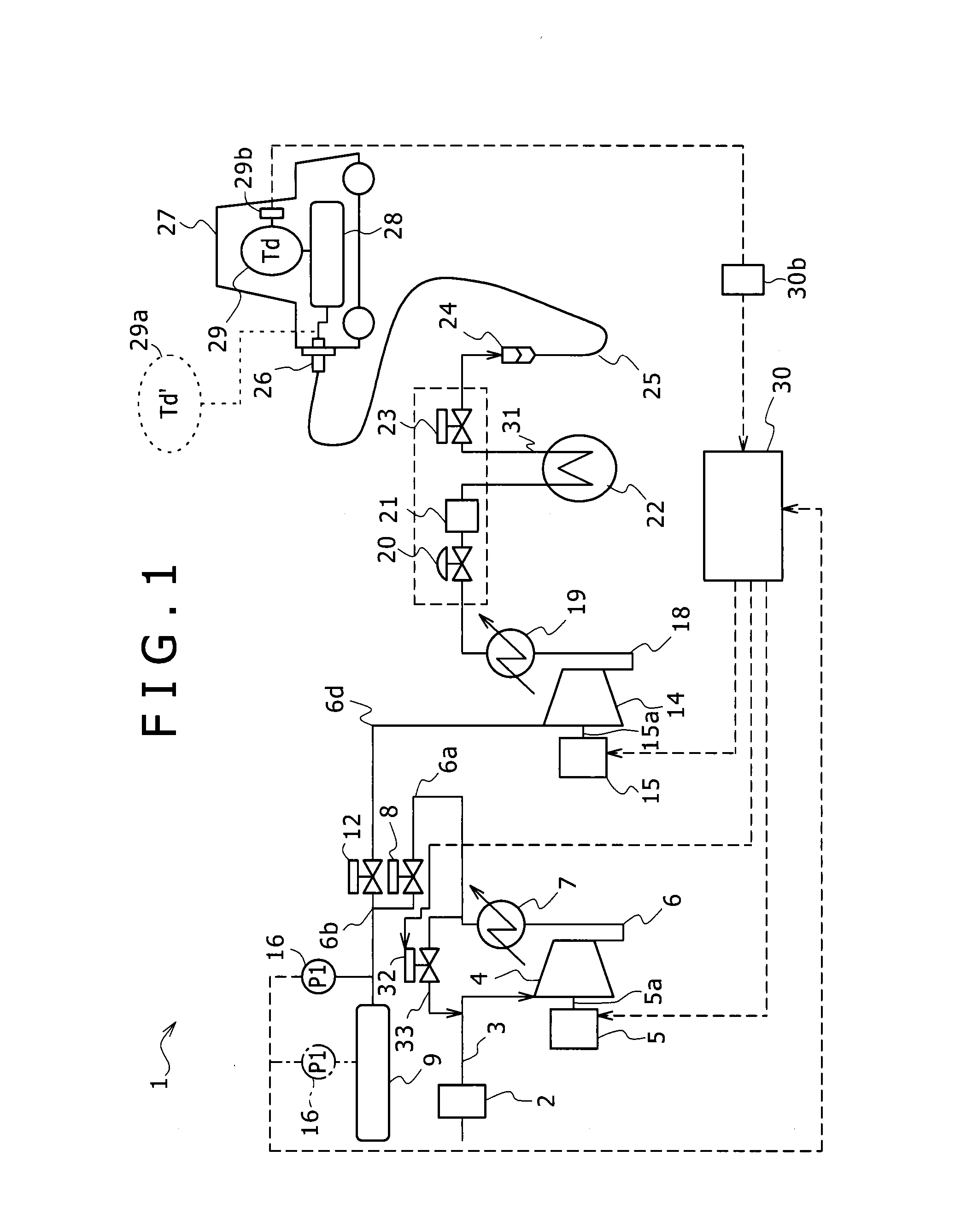
[0081]FIG. 4 illustrates a configuration of a hydrogen station 1b according to a second embodiment of the present invention. The hydrogen station 1b has substantially the same configurations as those of the hydrogen station 1 according to the first embodiment. Furthermore, the same reference signs will be given to the same configurations as those of the first embodiment and the specific description thereof will not be repeated.

[0082]The hydrogen station 1b of this embodiment is different from the hydrogen station 1 of the first embodiment in that two intermediate pressure accumulators (the first and second intermediate pressure accumulators 9 and 11) are provided and a flywheel 31 is provided in the drive shaft 15a connecting the high-pressure-side reciprocating compressor 14 to the driver 15. Further, the hydrogen station 1b of this embodiment is different from the hydrogen station 1 of the first embodiment in that the bypass passage 33 is not provided.

[0083]Specifically, the confi...

third embodiment

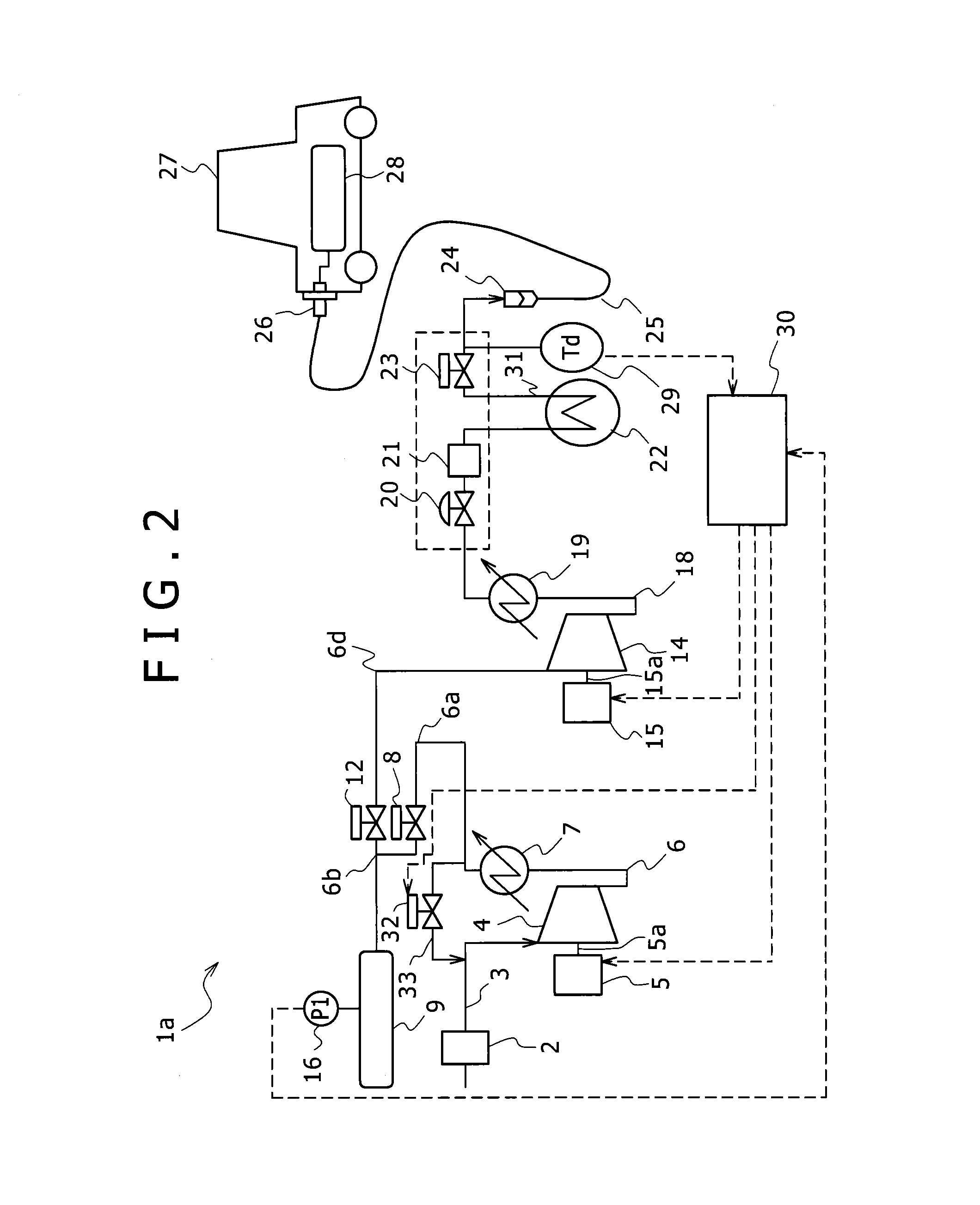
[0095]FIG. 5 illustrates a configuration of a hydrogen station 1c according to a third embodiment of the present invention. The hydrogen station 1c has substantially the same configurations as those of the hydrogen station 1b according to the second embodiment. Furthermore, the same reference signs will be given to the same configurations as those of the second embodiment and the specific description thereof will not be repeated.

[0096]In the hydrogen station 1b of the second embodiment, the revolution of the driver 15 is controlled based on the temperature Td, but the hydrogen station 1b of this embodiment has a difference in that the opening degree of the adjustment valve 32 is adjusted based on the temperature Td so as to adjust the amount (the return amount) of the hydrogen returned from the discharge side of the high-pressure-side reciprocating compressor 14 to the suction side thereof through a return passage 33 to be described later.

[0097]In the hydrogen station 1c, the return...


PUM

PropertyMeasurementUnit
inversion temperatureaaaaaaaaaa
pressureaaaaaaaaaa

Abstract

Provided is a hydrogen station that supplies hydrogen to an external hydrogen tank, the hydrogen station including: a reciprocating compressor that is driven by a driver of which revolution is controllable; a cooling device that is capable of cooling hydrogen supplied from the reciprocating compressor to the hydrogen tank; a temperature sensor that detects an internal temperature of the hydrogen tank or a temperature of the hydrogen supplied to the hydrogen tank; and a control unit that controls the revolution of the driver based on the temperature detected by the temperature sensor.

Description

TECHNICAL FIELD[0001]The present invention relates to a hydrogen station that supplies hydrogen to a fuel cell vehicle, a hydrogen vehicle, and the like.BACKGROUND ART[0002]In recent years, there have been concerns such as global warming and aerial pollution caused by carbon dioxide (CO2), nitrogen oxide (NOX), and suspended particulate matter (PM). For this reason, instead of an existing gasoline internal-combustion engine vehicle, a fuel cell vehicle (FCV) which is driven by using electric energy based on an oxidization reaction between hydrogen and oxygen in a fuel cell mounted on the vehicle has been gaining attention.[0003]The fuel cell vehicle does not discharge any toxic matter in addition to the above-described carbon dioxide and the like. Further, the fuel cell vehicle has energy efficiency better than that of the gasoline internal-combustion engine vehicle. Likewise, the fuel cell vehicle has various advantages that may not be obtained from the gasoline internal-combustion...

Claims


Application Information

Patent Timeline
Patent Type & Authority Applications(United States)
IPC IPC(8): F17C5/06
CPCF17C5/06F17C5/007F17C13/026F17C2205/0326F17C2205/0338F17C2221/012F17C2223/0123F17C2223/033F17C2225/0123F17C2225/036F17C2227/0164F17C2227/0185F17C2227/0337F17C2227/0388F17C2250/01F17C2250/032F17C2250/043F17C2250/0439F17C2250/0443F17C2260/023F17C2265/065F17C2270/0139Y02P90/45Y02E60/32
Inventor NAGURA, KENJITAKAGI, HITOSHI
Owner KOBE STEEL LTD
Why Eureka
Try Eureka