System And Method Of Tractor Control Based On Agricultural Implement Performance

a technology of agricultural implements and control systems, applied in the field of agricultural implements, can solve the problems of uneven seed distribution and excessive variation, and achieve the effect of reducing the magnitude of vibration and improving the performance of agricultural implements

Active Publication Date: 2014-07-17
CNH IND CANADA
View PDF7 Cites 33 Cited by
  • Summary
  • Abstract
  • Description
  • Claims
  • Application Information

AI Technical Summary

Benefits of technology

[0006]The present invention provides a method and system for controlling operation of a tractor and / or an agricultural implement being towed by the tractor to improve performance of the agricultural implement. A vibration sensor is mounted to the agricultural implement to detect the magnitude of vibration, or bounce, present on the agricultural implement. The vibration sensor generates a feedback signal corresponding to the magnitude of vibration and transmits it to a controller. Because the magnitude of the vibration is a function of several operating parameters, including, but not limited to, the speed at which the tractor is travelling and the downward pressure applied to agricultural implement, one or more additional sensors are provided to monitor these operating parameters. Each additional sensor generates a feedback signal corresponding to the operating parameter being monitored and transmits it to the controller. The controller is configured to generate a reference signal used to control an actuator as a function of the magnitude of vibration and of the operating parameter. The actuator is configured to control operation of the tractor and / or agricultural implement to reduce the magnitude of vibration on the agricultural implement.

Problems solved by technology

However, it is known that rough or uneven terrain can cause vibration, or bounce, in the row units, resulting in uneven distribution of seed or excessive variation in the depth of the furrow and / or the amount of soil packed over the furrow.

Method used


Image

  • System And Method Of Tractor Control Based On Agricultural Implement Performance
  • System And Method Of Tractor Control Based On Agricultural Implement Performance
  • System And Method Of Tractor Control Based On Agricultural Implement Performance

Examples


Embodiment Construction

[0022]The various features and advantageous details of the subject matter disclosed herein are explained more fully with reference to the non-limiting embodiments described in detail in the following description.

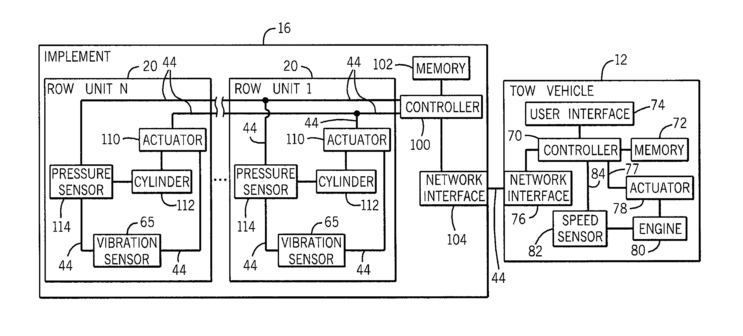
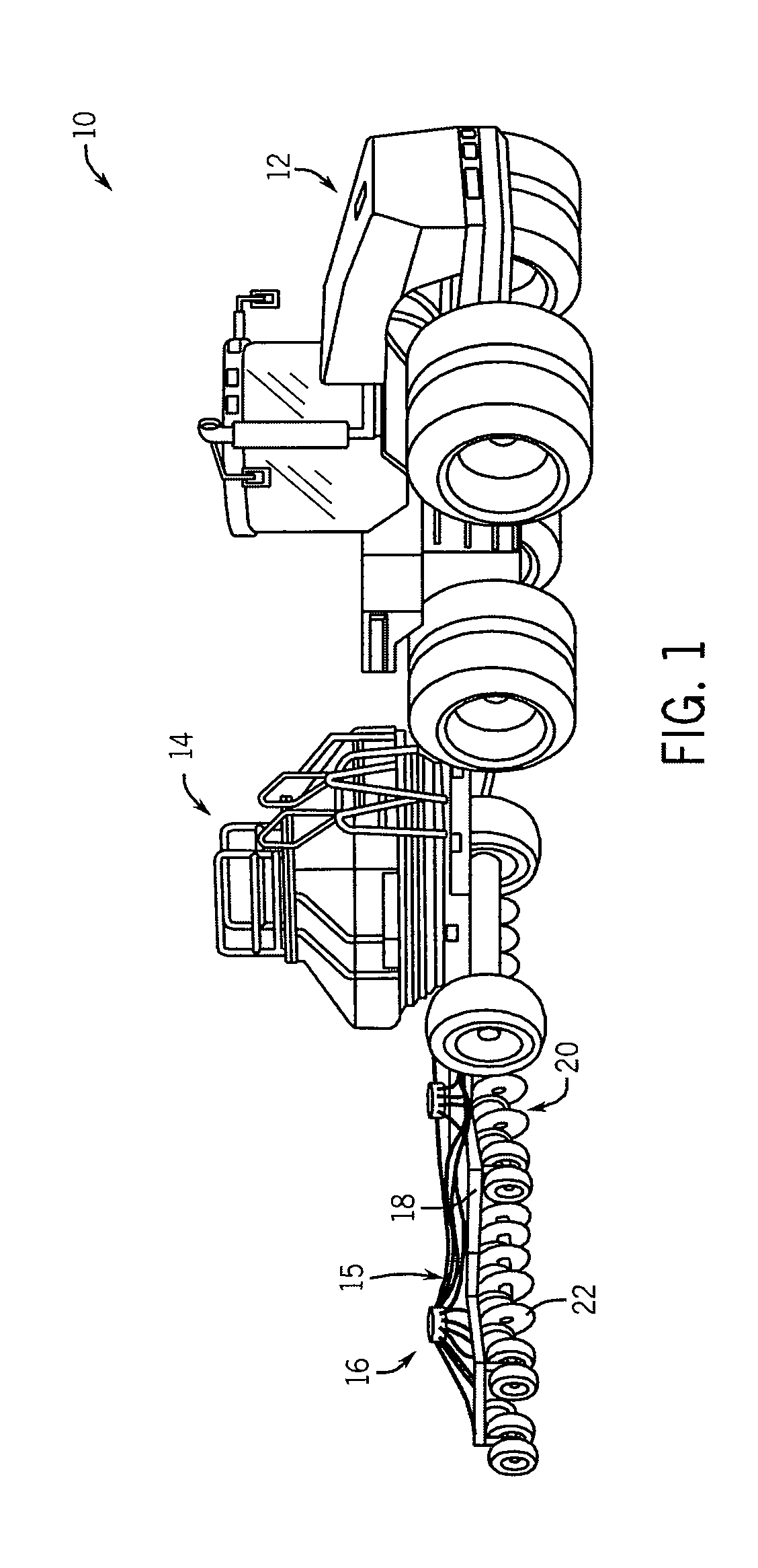
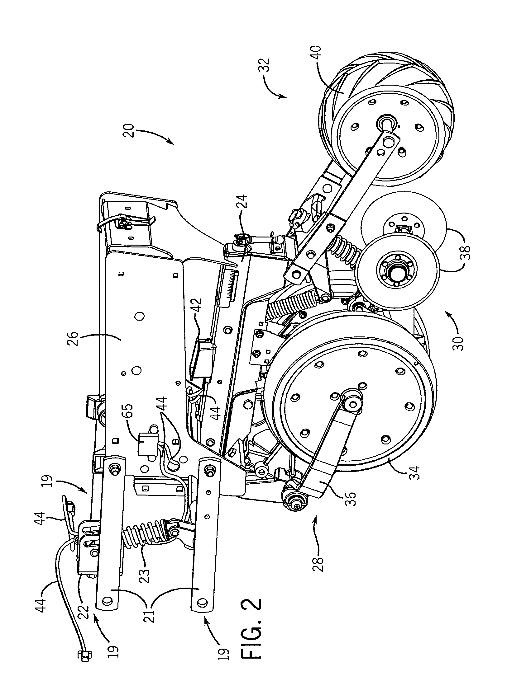
[0023]Referring now to the drawings, and more particularly to FIG. 1, an agricultural seeding system 10 is shown and is generally comprised of a tow vehicle such as a tractor 12, an air cart 14, and an air drill 16. The air cart 14 is hitched to the tractor 12 and the air drill 16 is hitched to the air cart 14 via an appropriate hitch member, such as a ball, clevis, or other coupling. The air drill 16 includes at least one frame member such as a tool bar 18, which is coupled to the hitch member, and a plurality of row units 20 coupled to the tool bar 18. According to one embodiment of the invention, each row unit 20 is configured to cut a furrow into the soil, distribute product, such as seed and / or fertilizer, in the furrow, and close the furrow over the distributed product...


PUM


Abstract

A method and system for controlling operation of a tractor and/or agricultural implement towed by the tractor is disclosed. A vibration sensor is mounted to the agricultural implement to detect the magnitude of vibration, or bounce, on the agricultural implement. Because the magnitude of the vibration is a function of several operating parameters including, but not limited to, the speed at which the tractor is travelling and the downward pressure applied to the agricultural implement, one or more additional sensors are provided to monitor these operating parameters. Each of the sensors generates a feedback signal and transmits it to the controller. The controller is configured to generate an reference signal to control an actuator as a function of the magnitude of vibration and the measured operating parameter. The actuator receiving the reference signal is configured to control operation of the tractor or agricultural implement to reduce the magnitude of vibration.

Description

BACKGROUND OF THE INVENTION[0001]The subject matter disclosed herein relates generally to agricultural implements towed behind a tractor, and in particular, to automatic control of the tractor and / or agricultural implement as a function of the vibration detected in the attached implement.[0002]One type of planting implement, sometimes referred to as an air drill, is towed behind a tractor and is commonly equipped with one or more row units. The row units are attached to the air drill frame by individualized arms or linkages which allow the row units to operate independently of another. This “independence” allows each row unit to independently respond to changes in terrain and field obstructions, for example, by moving in a vertical direction.[0003]Each row unit includes, for example, a ground engaging device such as a point, a shank, or a coulter disc to open a furrow in a field, a product distribution system to distribute product to the field, and a closing system to put dirt over ...

Claims


Application Information

Patent Timeline
Patent Type & Authority Applications(United States)
IPC IPC(8): F16F15/02A01B63/32A01B63/00
CPCF16F15/02A01B63/32A01B63/002A01B61/02A01B67/00A01C7/205A01B79/005
Inventor KOWALCHUK, TREVOR
Owner CNH IND CANADA
Why Eureka
Try Eureka