
Thermal energy storage for combined cycle power plants

a combined cycle and power plant technology, applied in the direction of indirect heat exchangers, machines/engines, lighting and heating apparatus, etc., can solve the problems of insufficient overcapacity, inability to quickly achieve rapid operation of ccpps, and inability to meet the needs of rapid operation, etc., to achieve convenient fluid flow, high thermal conductivity, and efficient response

Active Publication Date: 2014-07-24
RES FOUND THE CITY UNIV OF NEW YORK
View PDF14 Cites 26 Cited by
  • Summary
  • Abstract
  • Description
  • Claims
  • Application Information

AI Technical Summary

Benefits of technology

The patent describes a method for a combined cycle power plant to efficiently handle changes in load. It involves using a thermal storage tank and a flow path for fluid to exit the gas turbine. A storage medium made of high thermal conductivity heat resistance particles is placed in the flow path, which allows the fluid to flow in a specific direction. The particles are arranged in a packed bed with dimensions chosen to minimize back pressure to the gas turbine. This method helps the power plant to quickly adjust to changes in load by providing a flow path for the excess fluid and ensuring efficient use of the gas turbine.

Problems solved by technology

Since gas turbines have a very low turndown ratio, they can lose efficiency very rapidly when power is below maximum.
The conventional CCPPs are not suitable for rapid load following for grid regulation and there is not enough overcapacity to enable such operation as a practical matter.

Method used


Image

  • Thermal energy storage for combined cycle power plants
  • Thermal energy storage for combined cycle power plants
  • Thermal energy storage for combined cycle power plants

Examples


Embodiment Construction

[0014]The following detailed description is of the best currently contemplated modes of carrying out these teachings. The description is not to be taken in a limiting sense, but is made merely for the purpose of illustrating the general principles of these teachings, since the scope of these teachings is best defined by the appended claims. Although the teachings have been described with respect to various embodiments, it should be realized these teachings are also capable of a wide variety of further and other embodiments within the spirit and scope of the appended claims.

[0015]As used herein, the singular forms “a,”“an,” and “the” include the plural reference unless the context clearly dictates otherwise.

[0016]Except where otherwise indicated, all numbers expressing quantities of ingredients, reaction conditions, and so forth used in the specification and claims are to be understood as being modified in all instances by the term “about.” Accordingly, unless indicated to the contra...


PUM


Abstract

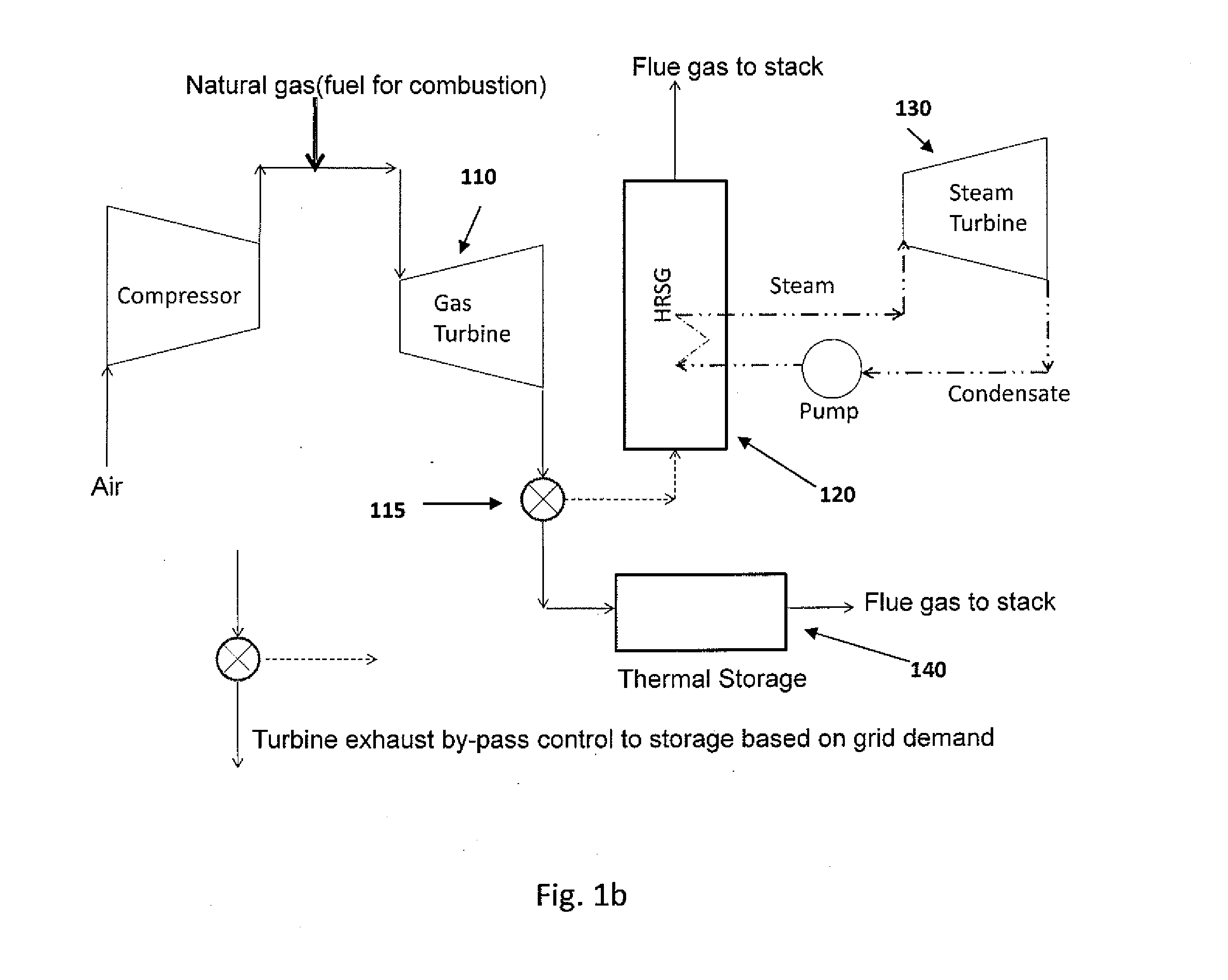
Thermal storage systems that preferably do not create substantially any additional back pressure or create minimal additional back pressure and their applications in combined cycle power plants are disclosed. In one embodiment of the method for efficient response to load variations in a combined cycle power plant, the method includes providing, through a thermal storage tank, a flow path for fluid exiting a gas turbine, placing in the flow path a storage medium comprising high thermal conductivity heat resistance media, preferably particles, the particles being in contact with each other and defining voids between the particles in order to facilitate flow of the fluid in a predetermined direction constituting a longitudinal direction, arrangement of the particles constituting a packed bed, dimensions of the particles and of the packed bed being selected such that a resultant back pressure to the gas turbine is at most a predetermined back pressure.

Description

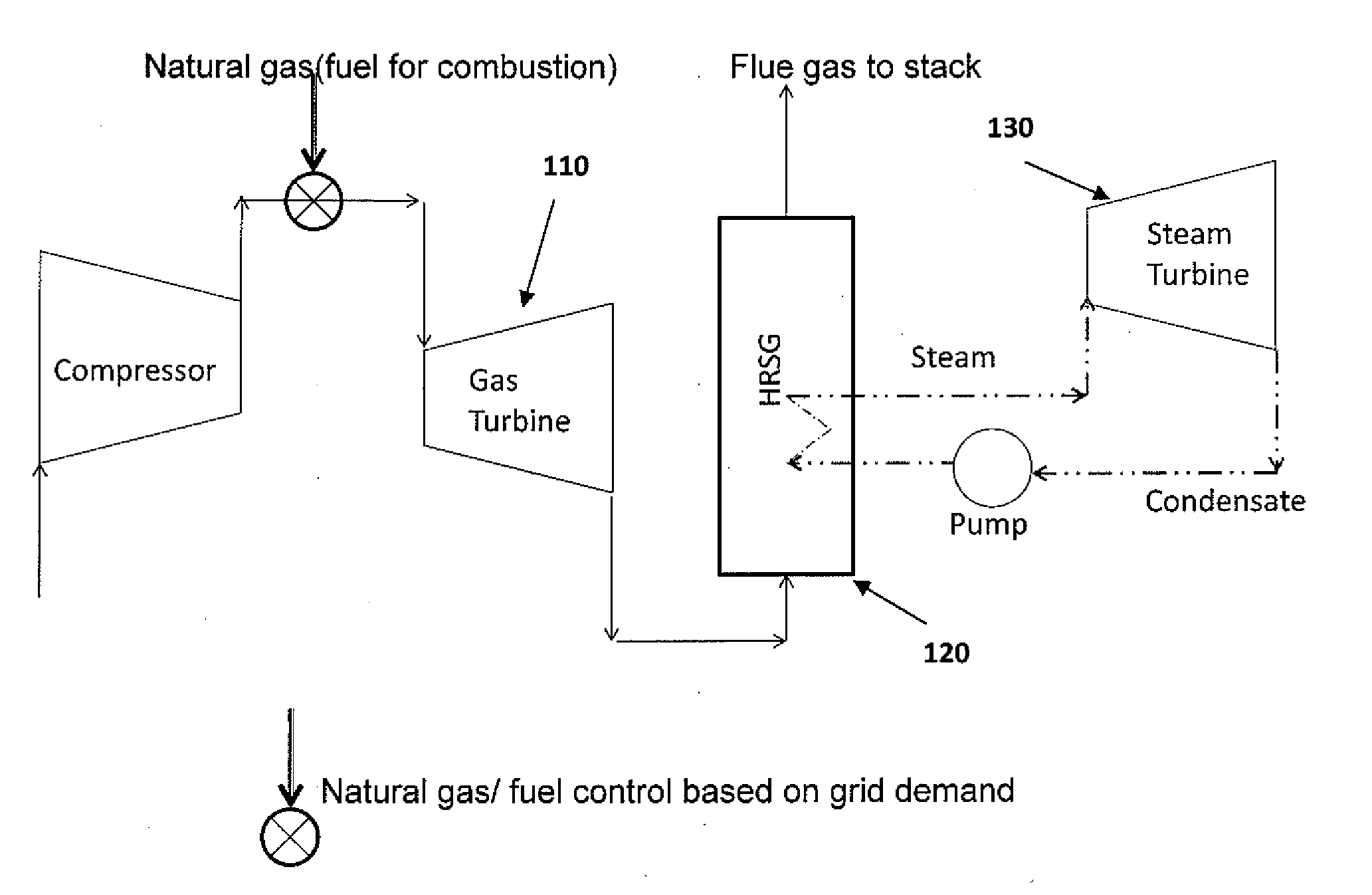
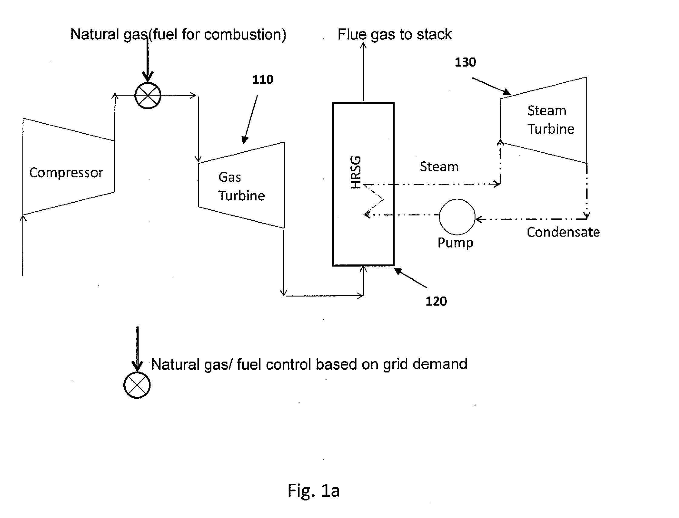
BACKGROUND[0001]One reason for the increased need for storage is that the technology for generating electricity has changed Standard combined cycle power plants(CCPP) used more commonly can be described by FIG. 1a. These plants provide a large fraction of the electric energy in the world and their use is growing fast (reaching over 20% of installed capacity in the U.S.). During normal operation, compressed air is introduced to a combustion chamber with natural gas or other fuel introduced in a controlled way. The high temperature (1100-1200° C.) gases which are produced as a result of this combustion are introduced to gas turbine 110. The exhaust gases after the expansion in the gas turbine 110 have much lower pressure (barely sufficient above atmospheric pressure in order to flow). The temperature of these exhaust gases is 550-600° C. resulting in the exhaust gases carrying high grade energy, which is recovered in a heat recovery steam generator (HRSG) 120 by generated steam in a s...

Claims


Application Information

Patent Timeline
IPC IPC(8): F01K3/02F01K13/02F01K23/10
CPCF01K3/00F01K23/10F01K3/02F01K13/02F01K23/101Y02E20/16F02C6/18F28D20/0056F05D2220/72F05D2260/42F28D17/005Y02E60/14F28D2020/0086F28D17/04F02C6/14
Inventor SHINNAR, REUELBINDRA, HITESH
Owner RES FOUND THE CITY UNIV OF NEW YORK
Learn More