Methods and structures for dynamically calibrating reference voltage

a reference voltage and dynamic calibration technology, applied in the direction of electric variable regulation, process and machine control, instruments, etc., can solve the problems of only reading trimming code, error up to 20 mv, and the operating margin of the regulator may not be affected,

Inactive Publication Date: 2014-07-24
FREESCALE SEMICON INC
View PDF10 Cites 37 Cited by
  • Summary
  • Abstract
  • Description
  • Claims
  • Application Information

AI Technical Summary

Problems solved by technology

Considering that several tens of milliVolts are eroded by current-resistance (IR) drop within the device and test equipment limitations for calibrating the band gap circuits to correct variation of low voltage detectors (LVD), the regulator may not have any operational margin.
Therefore a band gap circuit that generates the reference voltage may be calibrated or trimmed to achieve a small variation, however the trimming code can only be read as the system is starting and several complications arise.
An input referred offset voltage of 1 milliVolts (mV) can result in an error up to 20 mV.
A chopping technique has been previously used to reduce or completely eliminate the referred offset of the amplifier, however the resistance-capacitance (RC) filtering required to remove a high frequency signal causes only a high impedance output to be available from the amplifier.
The high impedance output is undesirable in environments that have a noisy ground reference.

Method used


Image

  • Methods and structures for dynamically calibrating reference voltage
  • Methods and structures for dynamically calibrating reference voltage
  • Methods and structures for dynamically calibrating reference voltage

Examples


Embodiment Construction

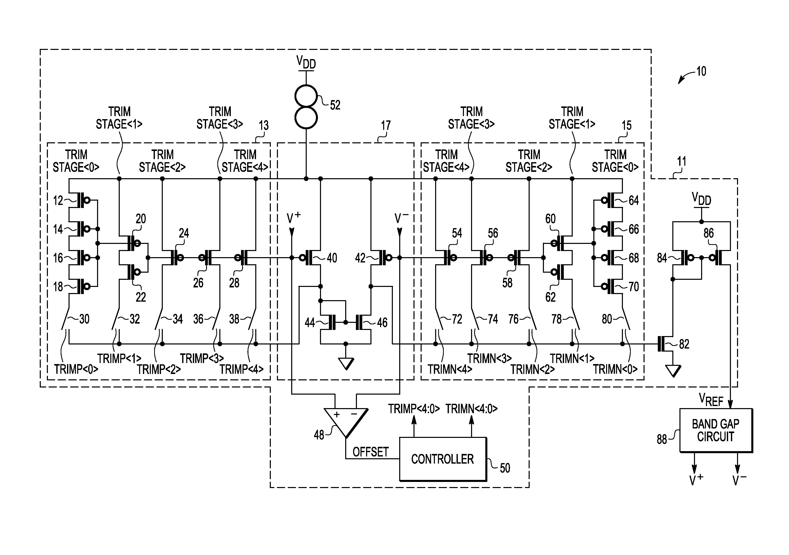
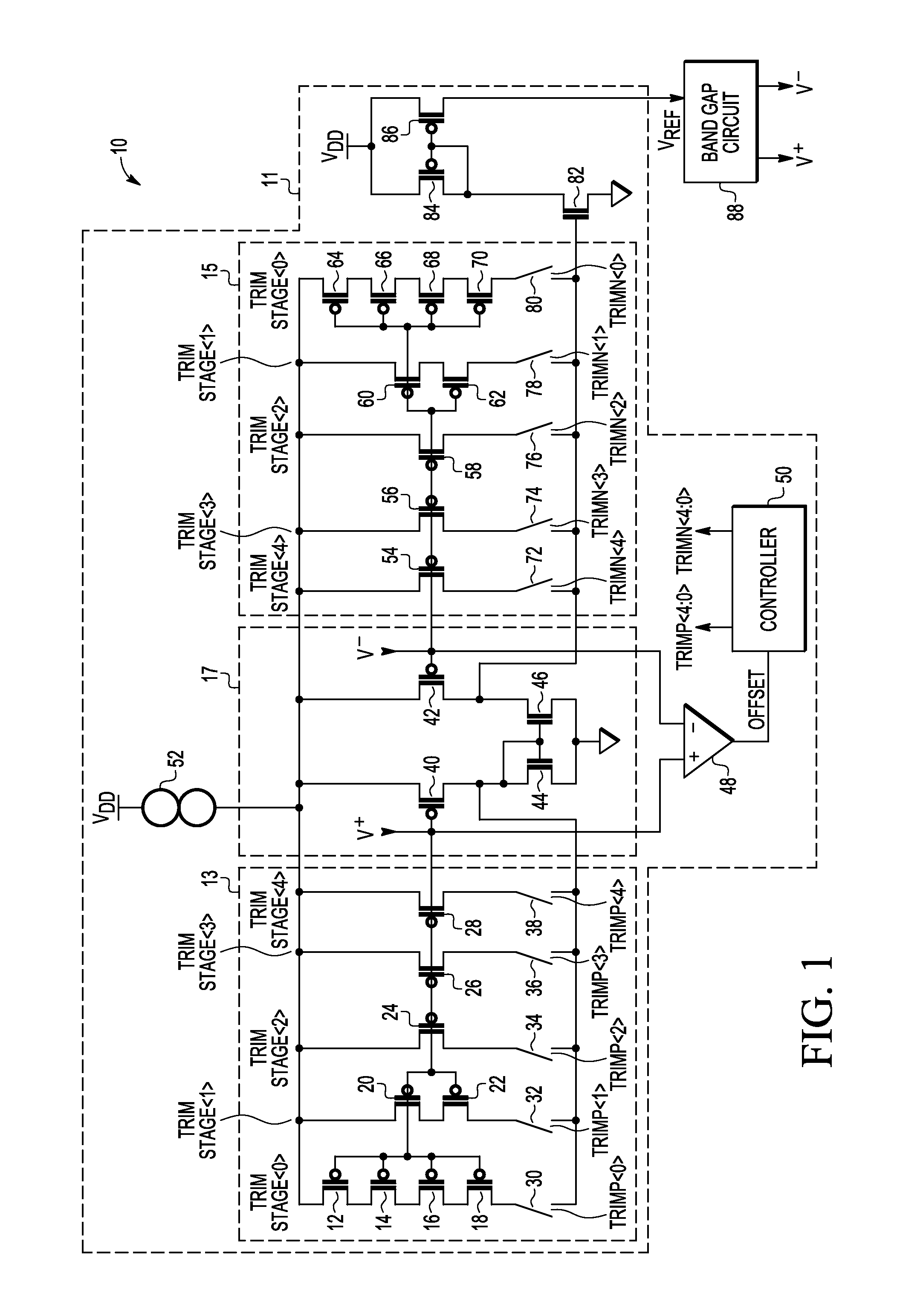
[0012]Embodiments of systems and methods disclosed herein use a switched capacitor gain stage to amplify offset at the input of an amplifier. Comparators in the switched capacitor gain stage then determine whether the amplified offset is positive or negative. A counter decrements or increments respective inputs to a differential pair of an operational transconductance amplifier to achieve a negligible amplifier offset. In this way the reference voltage has low impedance. No additional gain stage is required because the band gap system trims itself and achieves minimum variation without the need to retrieve trim data from a storage device such as flash memory even before the reference voltage is available to operate the storage device.

[0013]FIG. 1 illustrates a schematic diagram of an embodiment of a band gap system 10 in accordance with the present invention including a trimmable operational transconductance amplifier (OTA) 11 with trim circuits 13, 15 coupled to respective P-channe...


PUM


Abstract

A bandgap reference system has a bandgap circuit, an operational transconductance amplifier, and an offset controller. The bandgap circuit includes a pair of diode devices and has a reference terminal at which is provided a bandgap reference voltage. The bandgap circuit provides a differential output having a first output and a second output. The operational transconductance amplifier has a first input coupled to the first output of the bandgap circuit, a second input coupled to the second output of the bandgap reference circuit, and an output coupled to the reference terminal. The offset controller is coupled to the operational transconductance amplifier and to the first and second outputs of the bandgap circuit. The offset controller trims the operational transconductance amplifier as needed to ensure an offset of the operational transconductance amplifier is below a predetermined level.

Description

BACKGROUND[0001]1. Field[0002]This disclosure relates generally to semiconductor devices, and more specifically, to dynamically calibrating reference voltage in a band gap circuit.[0003]2. Related Art[0004]Advanced semiconductor devices require a supply voltage with 100 milliVolts (mV) range or less. Considering that several tens of milliVolts are eroded by current-resistance (IR) drop within the device and test equipment limitations for calibrating the band gap circuits to correct variation of low voltage detectors (LVD), the regulator may not have any operational margin. Yet, it is desirable to provide an LVD with small variation over corner voltages and a wide range of temperatures to allow a microprocessor core to run at tighter voltage with advantages of improved speed, reduced power consumption and leakage, and to increase the reliability of operation. In order to achieve precise LVDs, a precise voltage reference is required. Therefore a band gap circuit that generates the ref...

Claims


Application Information

Patent Timeline
Patent Type & Authority Applications(United States)
IPC IPC(8): G05F3/02
CPCG05F3/02G05F3/30
Inventor PIETRI, STEFANODAO, CHRIS C.REN, JUXIANG
Owner FREESCALE SEMICON INC
Why Eureka
Try Eureka