Check patentability & draft patents in minutes with Patsnap Eureka AI!

MEMS microdisplay optical imaging and sensor systems for underwater and other scattering environments

a micro-display optical imaging and sensor system technology, applied in the field of imaging systems and methods, can solve the problems of limited transmission of imaging information through difficult to characterize surfaces with conventional imaging system components, and large number of suspended particles in the field of view, so as to limit the transmission of optical data

Inactive Publication Date: 2014-07-24
FLORIDA ATLANTIC UNIVERSITY
View PDF1 Cites 41 Cited by
  • Summary
  • Abstract
  • Description
  • Claims
  • Application Information

AI Technical Summary

Benefits of technology

The invention is about a system and method for imaging from remote positions where visibility is limited. The system includes a transmitter assembly and a receiver assembly, with a microdisplay device that generates a 1D pattern of light to illuminate a target area. The light is scattered by the target area, and the receiver assembly collects the scattered light. The system uses a distributed compressive sensing technique to generate sensor information about the target area. The sensor information can be used to create an image of the target area. The system can be used on a moving platform, and the method includes initializing the system and performing a reconstruction process to assemble an image of the target area. The technical effects of the invention include improved imaging from remote positions and reduced sensor information requirements.

Problems solved by technology

In both terrestrial and submarine environments there are situations in which the transmission of imaging information through the field of view is limited rendering it difficult to characterize surfaces with conventional imaging system components such as, for example, a CCD-based imaging device and a divergent illumination source.
One common limiting factor is the presence of a large number of suspended particles in the field of view.
Not only does this result in significant back scattering of light, but it also contributes to transmission loss of imaging detail.
Typically, when the predominant component of energy received by the imaging device is attributable to scattered light, the signal-to-noise ratio is too low to provide useful information.
Summarily, both classes of extended range underwater imagers ultimately are limited in range by the cumulative effects of forward scattering events and divergence of the illumination, particularly as the reflected signal travels from the target region to the imaging system.
Scattering causes losses in contrast, resolution and signal to noise ratio (SNR).
These losses are particularly problematic at and near the range limit of operation.
Relatively small depth of field (DOF) has also been a disadvantage in prior LLS system designs.
This is particularly problematic when imaging in a dynamic undersea environment in which there is significant variation in optical transmission properties or in sea bed surface features or in which there is significant variation in platform altitude or attitude.
With a small DOF each of these factors can lead to unacceptable degradation in image quality or complete signal loss.
Range-gated imagers have also had inherent disadvantages in addition to limitations in imaging distance.
For example, variations in distance between the system and a target surface result in a change in the required delay time of the gating function used to selectively acquire photons returning from the target.
Based on the foregoing it is apparent that both classes of extended range imagers have performance limitations restricting usefulness in a variety of potential applications including, for example, smoke-filled environments, fog, adverse weather conditions and underwater imaging.
This is particularly desirable when imaging target surfaces having a high spatial frequency, as the combined effects of forward scattering and blurring, due to the limited DOF, further limit the achievable resolution.
However, provision of mechanically rotatable polygonal mirrors in scanners poses a significant addition to the system size and cost and may affect reliability.
Efforts to build small, more compact laser line scanners of this type are subject to limitations because of the mechanical nature of the rotating mirror systems.
Another intrinsic limitation of the raster scanning based techniques such as the LLS system is that in order to maintain the image resolution with increased platform speed, higher laser repetition rate will be required.
This in turn affects the system cost and complexity (i.e., noise mitigation of wider bandwidth electronics).

Method used


Image

  • MEMS microdisplay optical imaging and sensor systems for underwater and other scattering environments
  • MEMS microdisplay optical imaging and sensor systems for underwater and other scattering environments
  • MEMS microdisplay optical imaging and sensor systems for underwater and other scattering environments

Examples


Embodiment Construction

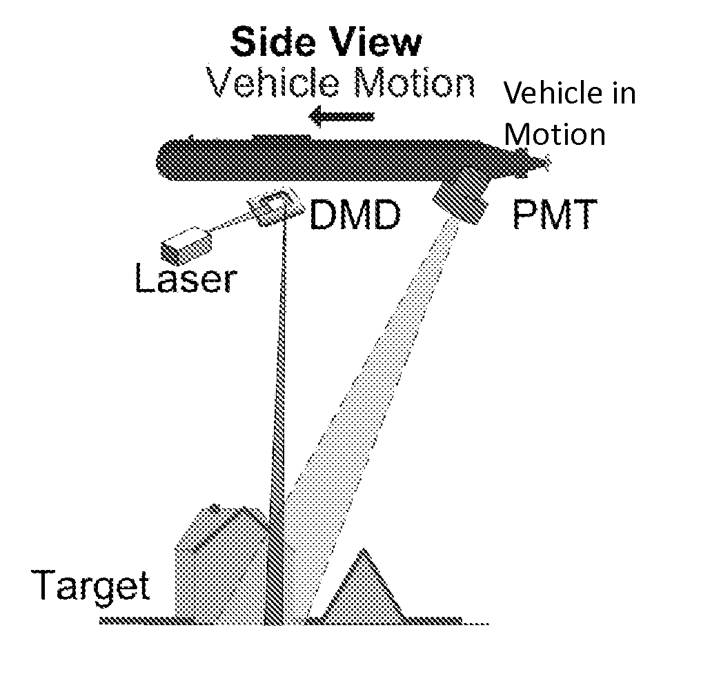
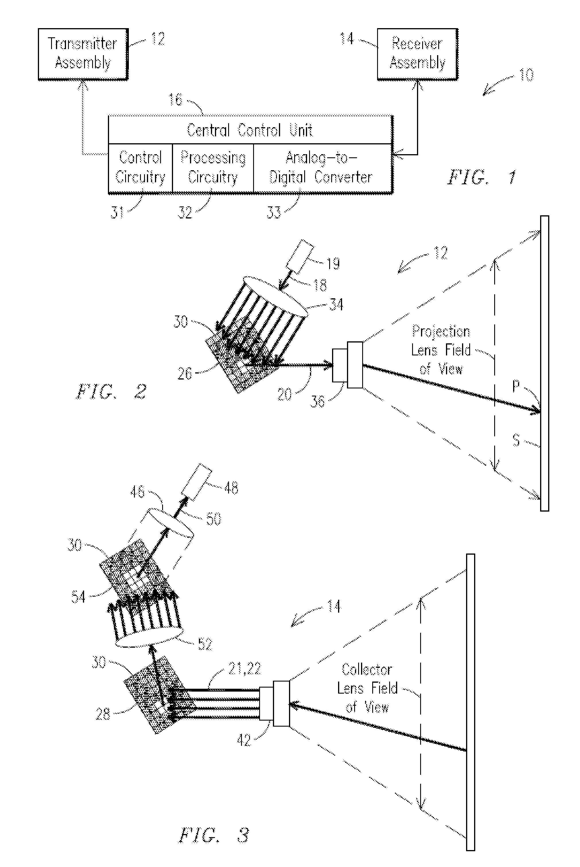
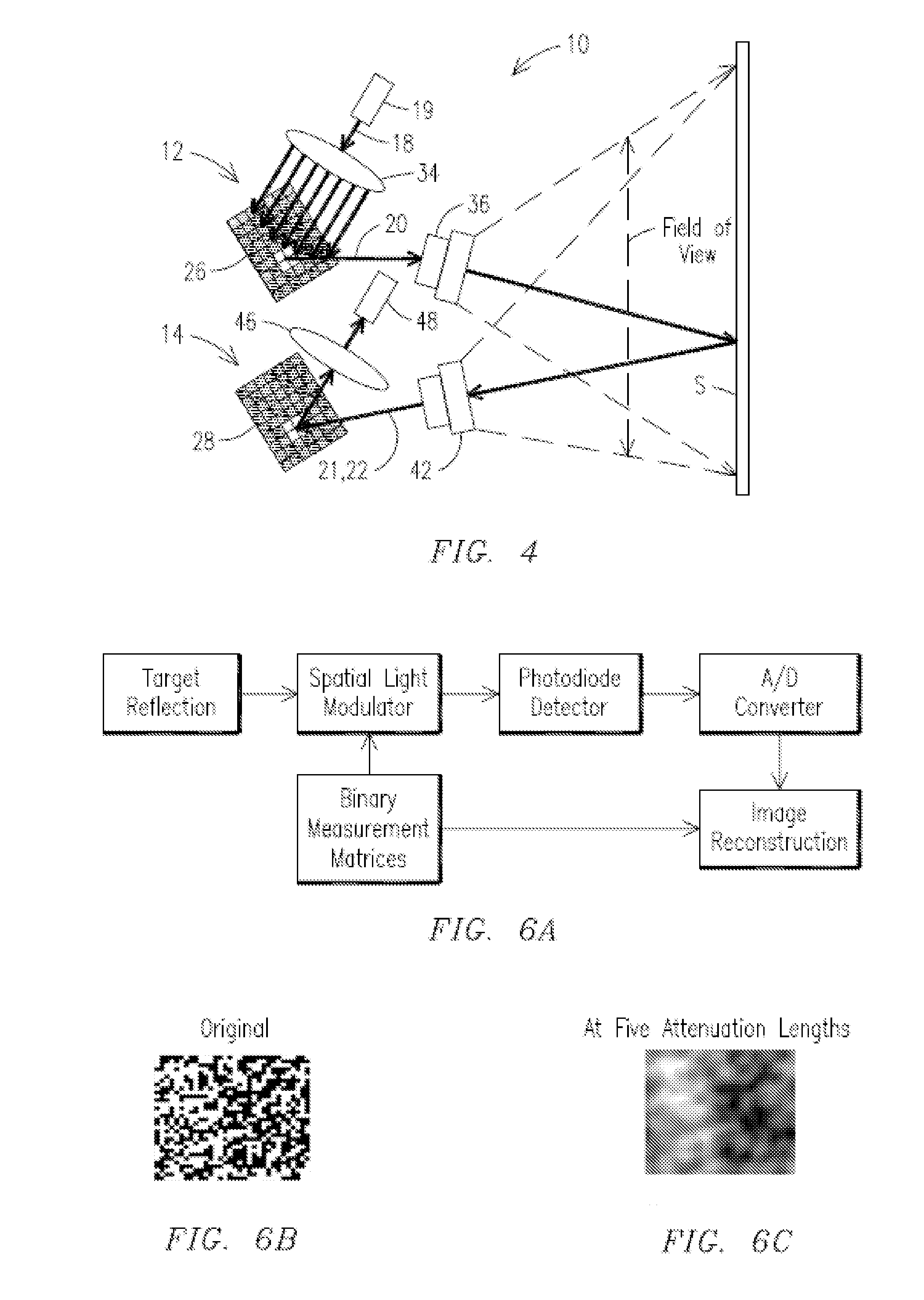
[0065]Before describing in detail the particular methods and apparatuses related to embodiments of the invention, it is noted that the present invention resides primarily in a novel and non-obvious combination of components and process steps. So as not to obscure the disclosure with details that will be readily apparent to those skilled in the art, certain conventional components and steps have been omitted or presented with lesser detail, while the drawings and the specification describe in greater detail other elements and steps pertinent to understanding the invention. Further, the following embodiments do not define limits as to structure or method according to the invention, but only provide examples which include features that are permissive rather than mandatory and illustrative rather than exhaustive.

[0066]The embodiments described herein are based in part on concepts disclosed in US Patent Application Publication No. 20080218821, now incorporated herein by reference, titled...


PUM


Abstract

A sensing system is provided that includes a transmitter assembly with a light source and a microdisplay device, wherein the transmitter assembly defines an optical beam transmission path to provide illumination of a substantially one-dimensional (1D) region of a target area, the microdisplay device comprising a plurality of controllable elements for causing the illumination to be a substantially 1D pattern of light along the 1D region. The system further includes a receiver assembly for defining a return optical signal transmission path from the 1D region and collecting return optical signals from the 1D region. The system also includes a processing component for generating sensor information associated with the 1D region by processing the return optical signals from the 1D region with return optical signals from adjacent 1D regions using a distributed compressive sensing (DCS) technique.

Description

RELATED APPLICATIONS[0001]This application is a continuation-in-part of U.S. non-Provisional patent application Ser. No. 13 / 089,715, filed 19 Apr. 2011, which claims priority to U.S. Provisional Patent Application Ser. No. 61 / 325,449, filed 19 Apr. 2010, the contents of both of which are incorporated herein by reference in their entirety.STATEMENT REGARDING FEDERALLY SPONSORED DEVELOPMENT[0002]Development of this invention was supported in part by Award No. N00014-09-1-0714, awarded by the United States Office of Naval Research. Accordingly, the United States Government may have certain rights in this invention.FIELD OF THE INVENTION[0003]This application relates generally to imaging systems and methods and, in particular, has application in characterization of surfaces, e.g., reflectance profiles, from remote positions wherein visibility through a medium may be range limited or otherwise obscured by, for example, light scattering effects or other phenomena which can limit transmiss...

Claims


Application Information

Patent Timeline
IPC IPC(8): G01N21/55
CPCG01N21/55G01N2021/1793G01N2201/0675G01N21/49G01N21/47
Inventor OUYANG, BINGDALGLEISH, FRASERDALGLEISH, ANNI
Owner FLORIDA ATLANTIC UNIVERSITY
Features
  • R&D
  • Intellectual Property
  • Life Sciences
  • Materials
  • Tech Scout
  • Unparalleled Data Quality
  • Higher Quality Content
  • 60% Fewer Hallucinations
Learn More