Differential phase contrast imaging with energy sensitive detection

Active Publication Date: 2014-07-24
KONINKLJIJKE PHILIPS NV
View PDF14 Cites 31 Cited by
  • Summary
  • Abstract
  • Description
  • Claims
  • Application Information

AI Technical Summary

Benefits of technology

[0011]In such a way, artifacts in the image data that are based on phase wrappin

Problems solved by technology

When different kinds of tissue with similar absorption cross-sections are under examination (for example in mammography or angiography), the contrast of X-ray abso

Method used


Image

  • Differential phase contrast imaging with energy sensitive detection
  • Differential phase contrast imaging with energy sensitive detection
  • Differential phase contrast imaging with energy sensitive detection

Examples


Embodiment Construction

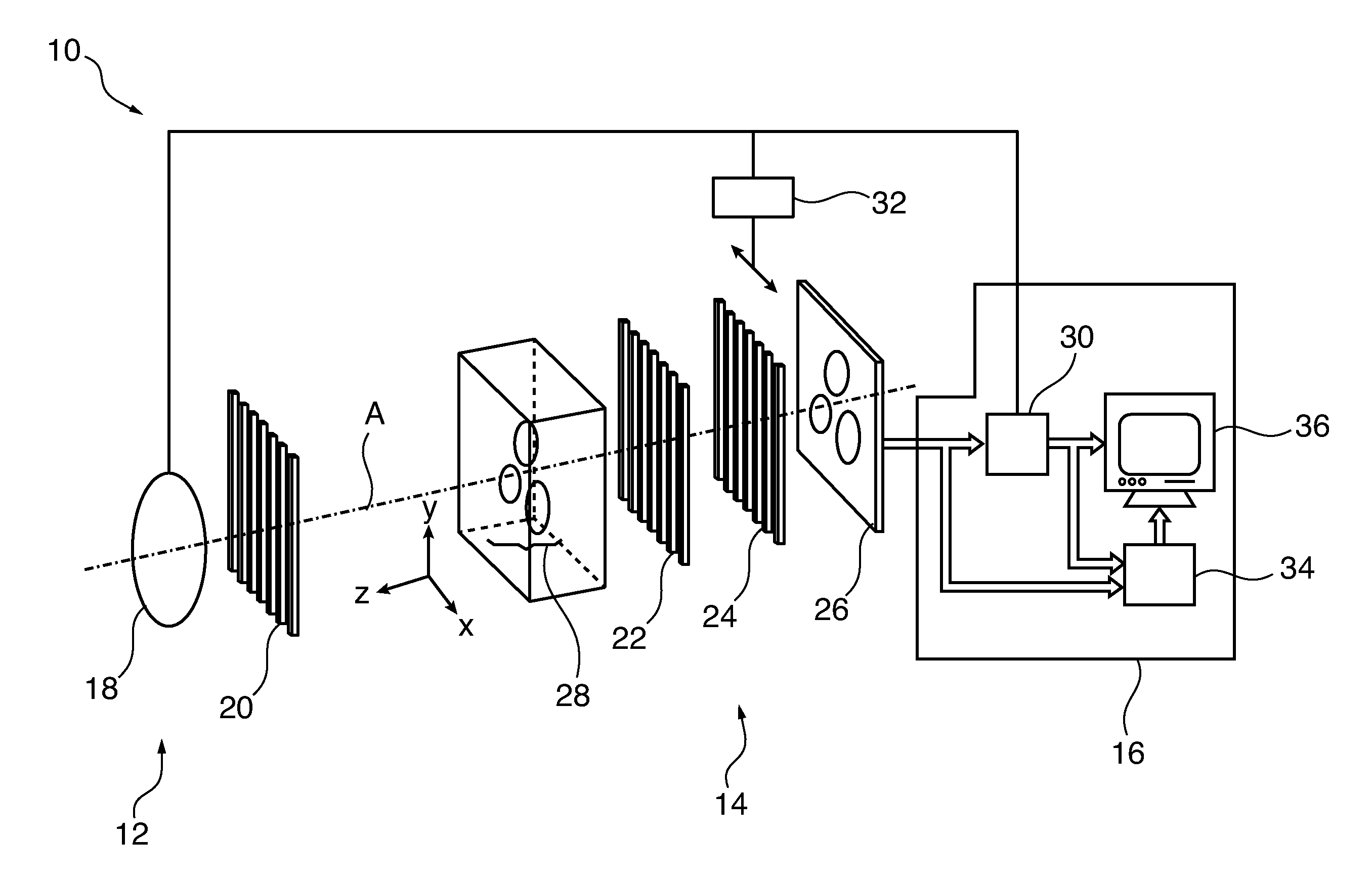
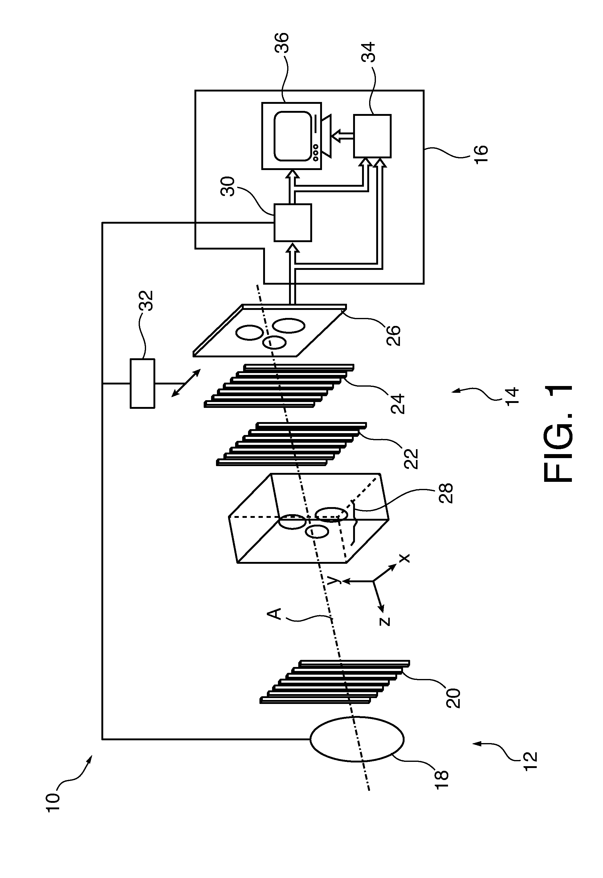
[0027]FIG. 1 schematically shows a differential phase imaging system 10 with a radiation source 10, a detector 12 and a controller 14.

[0028]The radiation source 10 may comprise an incoherent X-ray source 16, for example an X-ray tube 18, and a source grating 20 for achieving spatial beam coherence. The radiation source 10 may be adapted to generate a spatial coherent beam of radiation.

[0029]The detector 12 may comprise a phase grating 22, an absorber grating 24 and an X-ray detector element 26 adapted for detecting image data from X-rays radiated from the radiation source through an object of interest 28.

[0030]The source grating 20, the phase grating 22 and the absorber grating 24 have a plurality of equidistant X-ray absorbing (source and absorber grating) or phase shifting (phase grating) strips which extend in parallel in a direction normal to an optical axis A of the imaging system 10.

[0031]The phase grating 22 serves as a phase-shifting beam splitter, which transforms the varia...


PUM


Abstract

For correcting differential phase image data 52, differential phase image data 52 acquired with radiation at different energy levels is received, wherein the differential phase image data 52 comprises pixels 60, each pixel 60 having a phase gradient value 62a, 62b, 62c for each energy level. After that an energy dependent behavior of phase gradient values 62a, 62b, 62c of a pixel 60 is determined and a corrected phase gradient value 68 for the pixel 60 is determined from the phase gradient values 62a, 62b, 62c of the pixel 60 and a model for the energy dependence of the phase gradient values 62a, 62b, 62c.

Description

FIELD OF THE INVENTION[0001]The invention relates to differential phase contrast imaging. In particular, the invention relates to a method for correcting differential phase image data, a method for generating corrected differential phase image data, a computer program, a computer readable medium and differential phase imaging system.BACKGROUND OF THE INVENTION[0002]X-ray radiography and tomography are important methods for a variety of applications, for example non-destructive investigation of bulk samples, quality inspection of industrial products and non-invasive examination of anatomical structures and tissue regions of interest in the interior of a patient's body.[0003]X-ray imaging based on attenuation of X-rays may yield excellent results where highly absorbing anatomical structures such as bones are embedded in a tissue of relatively weakly absorbing material. This is due to the fact that the penetration depth of hard X-ray beams may be rather high, which allows for recording...

Claims


Application Information

Patent Timeline
IPC IPC(8): G06T7/00G01N23/04
CPCG01N23/046G06T7/0014G06T5/50G06T11/005G06T2211/408
Inventor KOEHLER, THOMASSCHLOMKA, JENS-PETER
Owner KONINKLJIJKE PHILIPS NV
Why Eureka
Try Eureka