Passive distance measurement using spectral phase gradients

a spectral phase gradient and distance measurement technology, applied in distance measurement, instruments, surveying and navigation, etc., can solve the problems of affecting the accuracy of spectral phase gradients, and the inability to detect the spectral phase gradient accurately, so as to avoid the dependence on a reference illumination, simplify both active and passive radar systems, and improve the accuracy

Active Publication Date: 2006-01-12
GURUPRASAD VENKATA
View PDF3 Cites 27 Cited by
  • Summary
  • Abstract
  • Description
  • Claims
  • Application Information

AI Technical Summary

Benefits of technology

[0074] The principal advantage of the present invention over most known distance measuring techniques is its truly passive nature. This enables its use over larger distances than any current technology, in both near and deep space, as it leads to an rmax∝P1/2 power-range law, and avoids dependence on a reference illumination.
[0075] Additional advantage is likely greater accuracy over non-parallax non-RTT methods such as the “standard candles” of astrophysics, its expected accuracy being comparable to those provided by spatial parallax. These advantages would likely hold well into inter-planetary and inter-galactic scales as well.
[0076] Its truly passive nature is of advantage also over current terrestrial passive radar systems, in being usable even in regions where the illumination by broadcast and cellular base station transmissions is unavailable or inadequate. In this case, it becomes limited to targets providing some electromagnetic emission, such as an infra-red heat signature, and reduces to a substitute for simple parallax. There is advantage over ordinary parallax, however, as the inventive method requires only one directional listening antenna.
[0077] The inventive method further provides a simple means for separating targets and target features by the...

Problems solved by technology

Problems of dependence on known illumination.
In all of the prior art, the need for illumination severely constrains radar technology.
Unfortunately, existing passive systems are again dependent on illumination from known source like radio and television broadcasting stations, as first described in the U.S. Pat. No. 3,812,493, issued in 1974, and in the recent years, from cellular telephone base stations.
Secondly, the large number of illuminating sources and the complexity of their signals makes the extraction of useful information from the reflections an extremely difficult computational problem.
In any case, the method is limited to regions of the earth where there are adequate illuminating sources, and also cannot be employed for ubiquitous applications being envisaged, like ground vehicular guidance and collision avoidance, nor for earth orbit or deep space tracking, where the illumination is generally absent.
However, these prior uses of chirps are for simplifying RTT measurement rather than eliminating it, and do not enable passive operation.
A fundamental difference remains, however, that the wavelet techniques are concerned with the scale distribution of the source signal, which cannot depend on the receiver's distance.
The first problem is that without the requisite manner of control which will be specified, the mechanism would produce frequency shifts in the received waves proportional to source distances.
A second problem particularly limiting the accidental category is that the invention requires an exponential profile of variation, or else the result is an even more complex form of dispersion from which the distance correlations are all the more difficult to recognize.
With the controlled transitions now provided by variable tuners and gratings, two problems have served to limit prior discovery, the first being that all such variable systems, like frequency modulation, are designed primarily for linear variation.
Secondly, the data is conceptually decoupled from the sources and their distances by sampling and digitization, making a reverse correlation with the source distances all the more inintuitive.
Thirdly, even with analogue recordings, the source distances generally manifest only as start-up delays ...

Method used


Image

  • Passive distance measurement using spectral phase gradients
  • Passive distance measurement using spectral phase gradients
  • Passive distance measurement using spectral phase gradients

Examples


Embodiment Construction

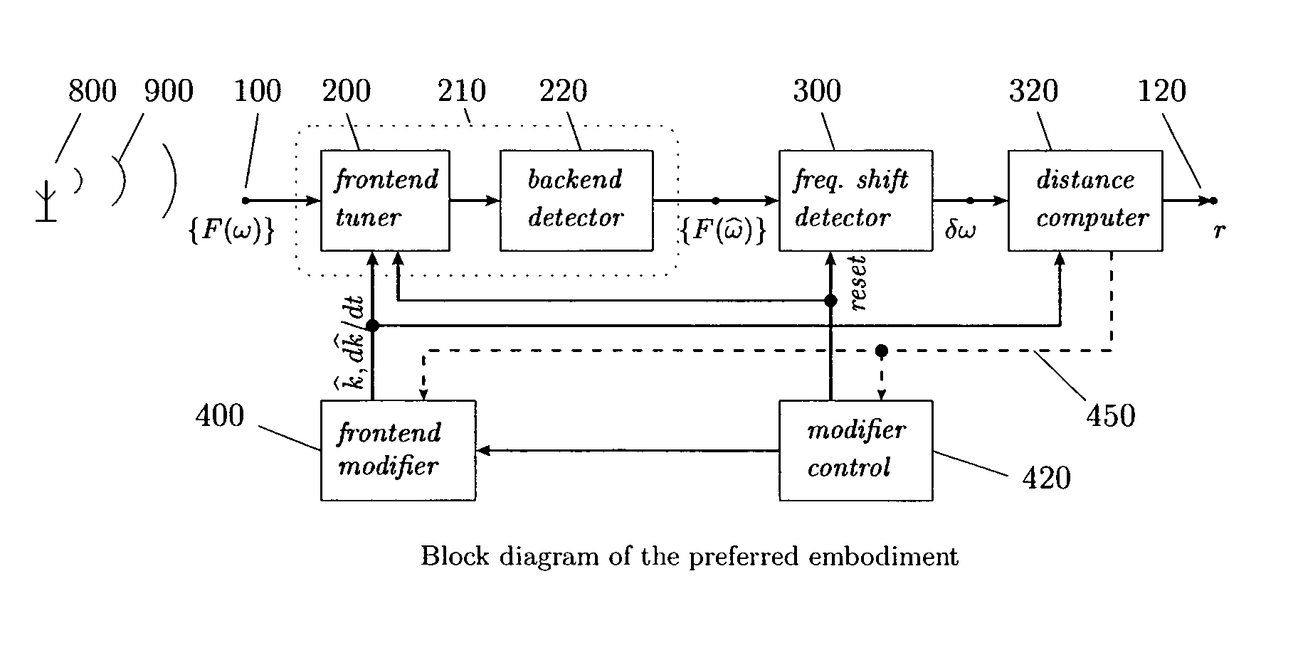
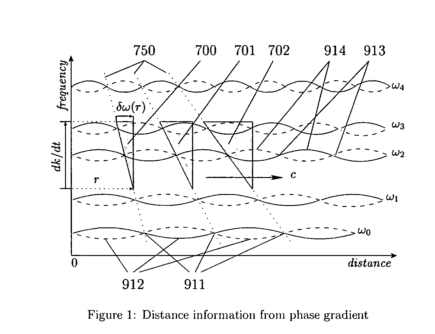
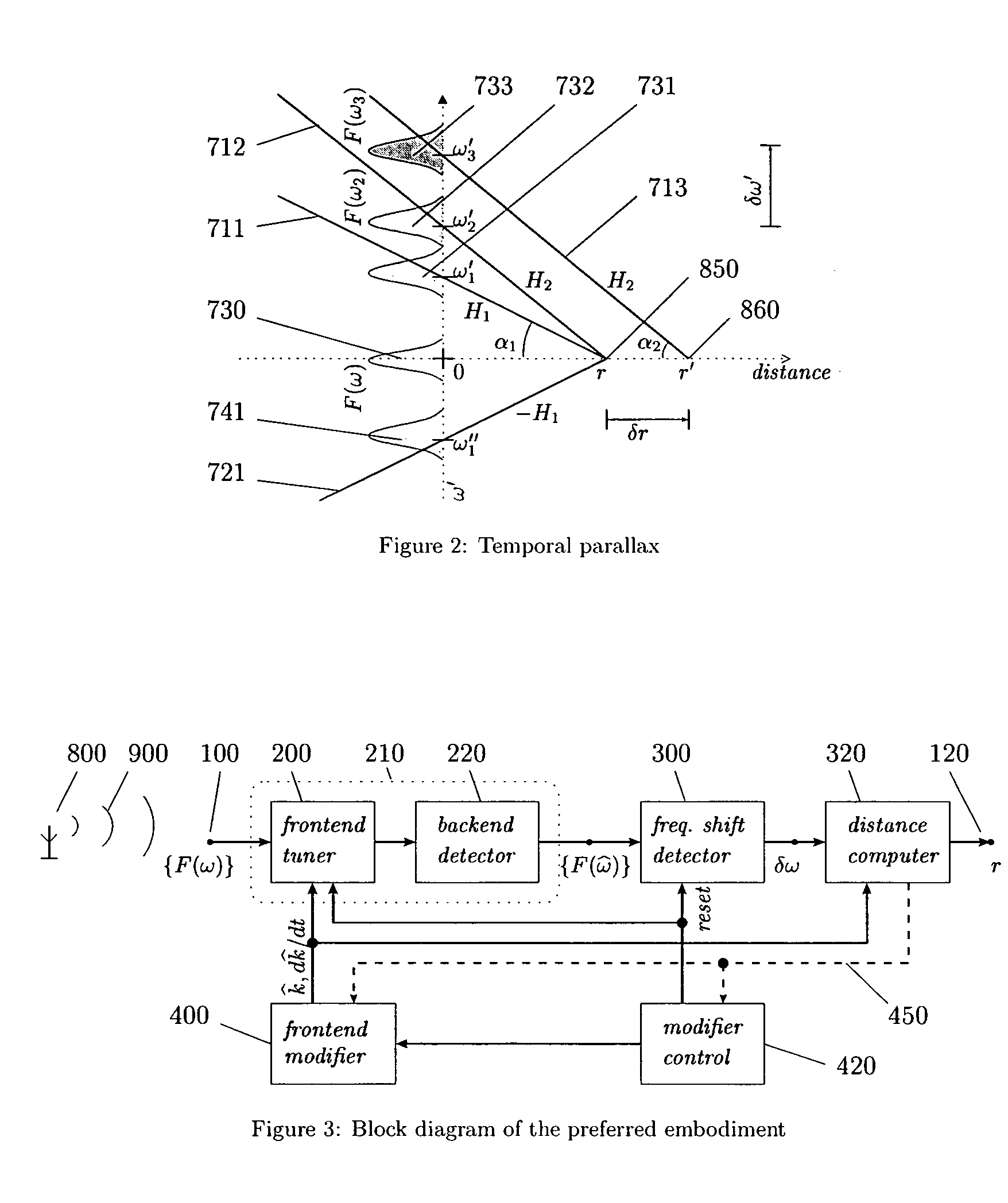
[0098] The invention is described in detail below, beginning with graphical explanations of the notions of phase gradients and temporal parallax, and of the core principle of the inventive procedure, followed by specification of the preferred embodiment, description of its operation and sample calculations for selecting β. Application of the embodiment to receivers using resonant cavities and tuned circuits, diffraction gratings or refraction, and sampling and computation of the spectra is discussed in that order, showing how the inventive frequency shift z results in each case to reveal the target distance r, per equation (1). Lastly, practical considerations and implications to physics are briefly discussed, in order to ensure sufficient understanding of the invention to enable its utilization in diverse forms and applications by those skilled in the related arts.

A. Principle of the Invention

[0099] The principle of the invention is best illustrated by the graph in FIG. 1 showin...


PUM


Abstract

General method for extracting source distance information from any kind of received radiation, including electromagnetic and acoustic, without involving round-trip time or phase in any form, and thus more truly passive than existing passive radars. The method exploits the facts that radiation from a real source must comprise wavepackets of nonzero bandwidth, that the individual frequency components of a wavepacket must have consistent phase at the source, and that their instantaneous phases must increase linearly along the path in proportion to the respective frequencies, so that the phase gradient across the components must be proportional to the distance travelled. The invention simplifies over naïve phase gradient measurement by scanning the phase gradient at a controlled rate, thereby converting the gradient into normalized frequency shifts proportional to the scanning rate and the source distance. It mimics the cosmological redshift and acceleration, but at measurable levels over any desired range and even with sound. Potential applications include stealth and “unjammable” radars for the military, ranging capability for emergency services, commodity low-power vehicular and personal radars, simplification and improvements in radar and diagnostic imaging, improved ranging in general all the way from ground to inter-galactic space, “interference-free” communication systems including radio and television receivers, source-distance (or range-division) multiplexing improved cellphone power control and battery life, and continuous, transparent diagnostics for optical fibres, integrated circuits and transmission lines.

Description

BACKGROUND OF THE INVENTION [0001] 1. Technical Field [0002] This invention generally pertains to the measurement of the distance to a remote object. More particularly, it concerns passive monostatic ranging, that is, measuring distance using electromagnetic or acoustic waves without illuminating, or querying, the object with electromagnetic or acoustic energy, and without involving spatial parallax. A fundamentally new way is disclosed for extracting distance information from the spectral phase profile, i.e. the phase distribution across a set of frequencies, in a received signal, without requiring it to be reflected or transponded. The invention more specifically concerns extraction of this information as a hitherto unrecognized effect of the wave nature of electromagnetism and sound similar to the Doppler effect, but using only the instantaneous source distance and receiver-side operations. [0003] 2. Brief Description of the Prior Art [0004] Problems of dependence on known illumi...

Claims


Application Information

Patent Timeline
IPC IPC(8): G01C3/08G01S11/02G01S19/19
CPCG01S11/02G01S11/12G01S11/14G01S7/4021G01S13/103G01S15/08G01S15/101G01S13/08
Inventor GURUPRASAD, VENKATA
Owner GURUPRASAD VENKATA
Why Eureka
Try Eureka