Regulated oil cooling system for a turbine engine with deicing of the nacelle

a turbine engine and nacelle technology, applied in the field of integrated turbine engines, can solve the problems of reducing affecting the efficiency of the turbine engine, and the system is not regulated according to the operational conditions, so as to reduce the size of the pump, discharging the heat, and discharging the heat.

Inactive Publication Date: 2014-07-24
SN DETUDE & DE CONSTR DE MOTEURS DAVIATION S N E C M A
View PDF4 Cites 55 Cited by
  • Summary
  • Abstract
  • Description
  • Claims
  • Application Information

AI Technical Summary

Benefits of technology

[0015]In a turbine engine according to the prior art without speed reducing gears for driving the fan, the head losses due to the heat exchangers in the bypass air flow correspond to 0.31% of the total, or a cost of 0.42% in the specific consumption of the turbine engine. The reducing gears that have to drive the fan in the planned new turbine engine architectures have to dissipate two to three times more heat. The external exchanger distributing small pipelines over the lip of the nacelle is capable of discharging this heat. Since the aerodynamic losses with the traditional exchangers are substantially proportional to the heat flux to be discharged, the use of the invention therefore represents a saving of 1% to 1.5% in consumption in cruising phase, based on the preceding data. This saving is therefore significant for an airplane engine.
[0016]Furthermore, the use of an air/oil exchanger situated in the bypass air flow with a variable capacity makes it possible to dimension the external exchanger for the flight conditions where the aerodynamic gain is most advantageous, while having the resource to correctly cool the oil with this second exchanger in the other conditions, for example during take-off and when taxiing...

Problems solved by technology

Furthermore, this has to be done with strong bulk constraints.
On the other hand, such equipment is subject to significant thermal stresses which reheat the lubrication oil all the more.
However, although the optimization of the heat exchange device has been studied, the problem of regulating the system according to operational conditions (flight, take-off, taxiing phase) remains.
In practice, if a large surface area, accordingly increasing its vulnerability, is not devoted to t...

Method used


Image

  • Regulated oil cooling system for a turbine engine with deicing of the nacelle
  • Regulated oil cooling system for a turbine engine with deicing of the nacelle
  • Regulated oil cooling system for a turbine engine with deicing of the nacelle

Examples


Embodiment Construction

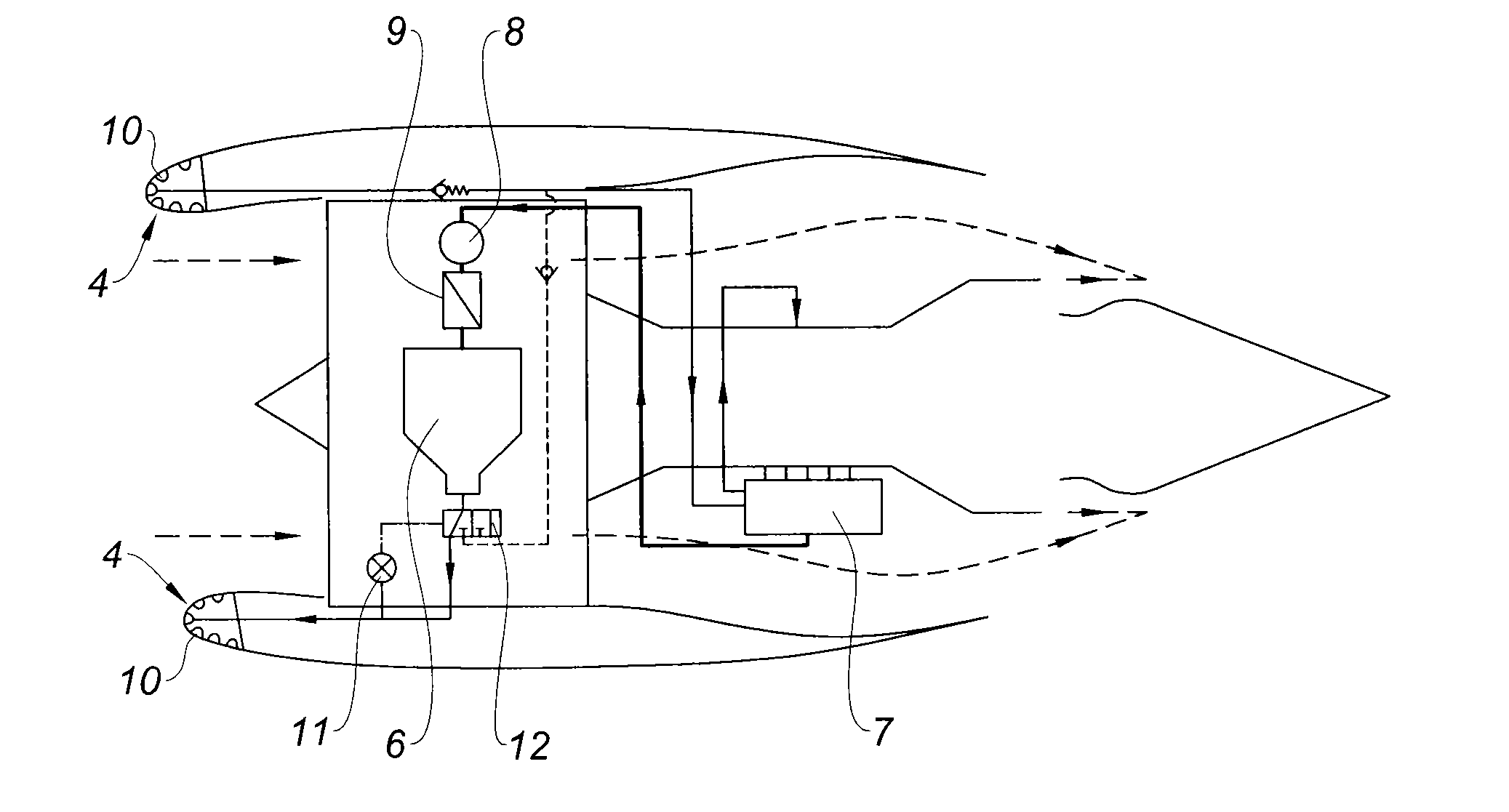
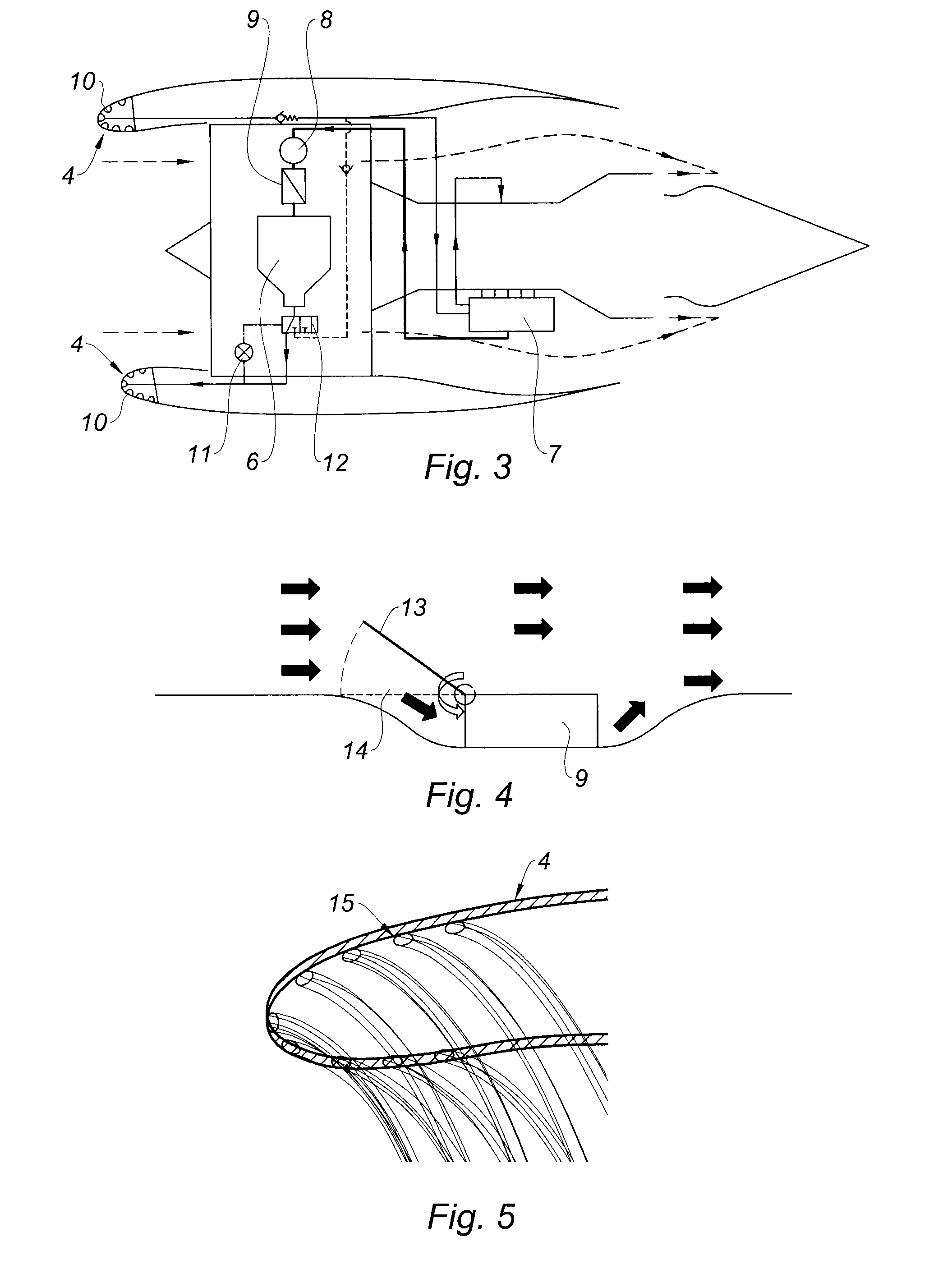
[0034]According to a preferential embodiment of the invention, as presented in principle in FIG. 3, the main differences compared to the prior art lie in the addition of a circuit sending the oil to a device (10), forming an external heat exchanger between the oil and the air inlet lip, and in the adaptation of the air / oil exchanger (9) in order to equip it with a device for varying its cooling capacity, with a control means for said device. Preferentially, the circuit comprising the external heat exchanger (10) is situated between the tank and the engine, therefore in series after the air / oil heat exchangers (9) situated in the cold zone. This arrangement makes it possible to limit the design modifications of the cooling circuit on an existing engine, notably without adding pumps in addition to those of the lubrication set (7) for sucking the oil into the external heat exchanger.

[0035]This heat exchanger (10) on the lip of the nacelle (5) fulfills two functions:[0036]it makes it po...


PUM


Abstract

The invention relates to an oil cooling system of a turbine engine installed in an aircraft comprising a circuit suitable for circulating the oil between the engine and at least one external heat exchanger placing the oil in thermal communication with a part of the lip of the nacelle, wherein it also comprises at least one air/oil heat exchanger placing the oil in thermal communication with the air circulating in the cold zone of the turbine engine, equipped with a device suitable for varying its oil cooling capacity, and with a control means for said cooling capacity variation device.

Description

BACKGROUND OF THE INVENTION[0001]The present invention relates to the field of the integration of turbine engines with which aircraft are equipped. It relates more particularly to the design of the lubrication system linked to the anti-icing system on aerodynamic elements such as the engine nacelle.DESCRIPTION OF THE PRIOR ART[0002]The thermal power to be discharged with the oil on turbine engines is constantly increasing, notably those equipped with a fan driven by a reducing gear. Furthermore, this has to be done with strong bulk constraints. In practice, on a turbine engine equipped with a mechanical transmission box situated around the propulsive core, represented in FIG. 1, most of the equipment is installed in the hot zone (3) around the engine compartments of restricted diameter comprising the combustion chamber and the compressor and the high pressure turbine, instead of the cold zone (2) of the fan compartment. This makes it possible to reduce the diameter of the nacelle an...

Claims


Application Information

Patent Timeline
IPC IPC(8): F02C7/14F02C7/047
CPCF02C7/047F02C7/14F01D25/12F01M5/002F02C7/224F16N39/02Y02T50/60F01D25/02
Inventor PATSOURIS, EMMANUELDEMOULIN, LAMBERT
Owner SN DETUDE & DE CONSTR DE MOTEURS DAVIATION S N E C M A
Why Eureka
Try Eureka