Processing biomass

a technology of biomass and irradiation, applied in nuclear engineering, nuclear elements, can solve the problems of high cost, low yield of cellulosic materials when contacted, and difficult access to complex matrix by enzymes and other chemical, biological and biological processes, etc., to achieve uniform irradiation, reduce the burden, and speed up the effect of speed

Active Publication Date: 2014-07-31
XYLECO INC
View PDF8 Cites 19 Cited by
  • Summary
  • Abstract
  • Description
  • Claims
  • Application Information

AI Technical Summary

Benefits of technology

[0022]A vibratory conveyor can provide an efficient mode of conveying biomass material under an irradiation source. The oscillating motions in all the possible combinations of x, y and z directions (where x is the direction of conveying, y is transverse to the direction of conveying, and z is in the direction perpendicular to conveying and orthogonal to x and y) for example, in the x direction, in x+z, and / or in x+y+z, provide many advantages while allowing conveying at a constant speed. The method and systems described can also provide an efficient mode of spreading out biomass material (for example,without additional spreading equipment or with fewer burdens on the optional spreading equipment) to an even thickness so that the irradiation can be substantially uniform. A further advantage over some other conveying systems and methods is that the biomass is turned and rotated, improving the irradiation uniformity, dosage averaging and cooling of the biomass. The uniform irradiation and improved dosage averaging can provide a material that has reduced recalcitrance throughout its bulk. Also, vibratory conveyors, for example, in comparison to other conveying systems and methods, can be lower in cost to operate. The methods and systems described herein can also reduce the intensity of irradiation needed to irradiate through the bulk of a biomass and reduce costs and increase safety of used, e.g., by reducing the shielding that is required.

Problems solved by technology

This produces a compact matrix that is difficult to access by enzymes and other chemical, biochemical and biological processes.
Cellulosic biomass materials (e.g., biomass material from which the lignin has been removed) is more accessible to enzymes and other conversion processes, but even so, naturally-occurring cellulosic materials often have low yields (relative to theoretical yields) when contacted with hydrolyzing enzymes.
While a number of methods have been tried to extract structural carbohydrates from lignocellulosic biomass, they are either are too expensive, produce too low a yield, leave undesirable chemicals in the resulting product, or simply degrade the sugars.

Method used


Image

  • Processing biomass
  • Processing biomass
  • Processing biomass

Examples


Embodiment Construction

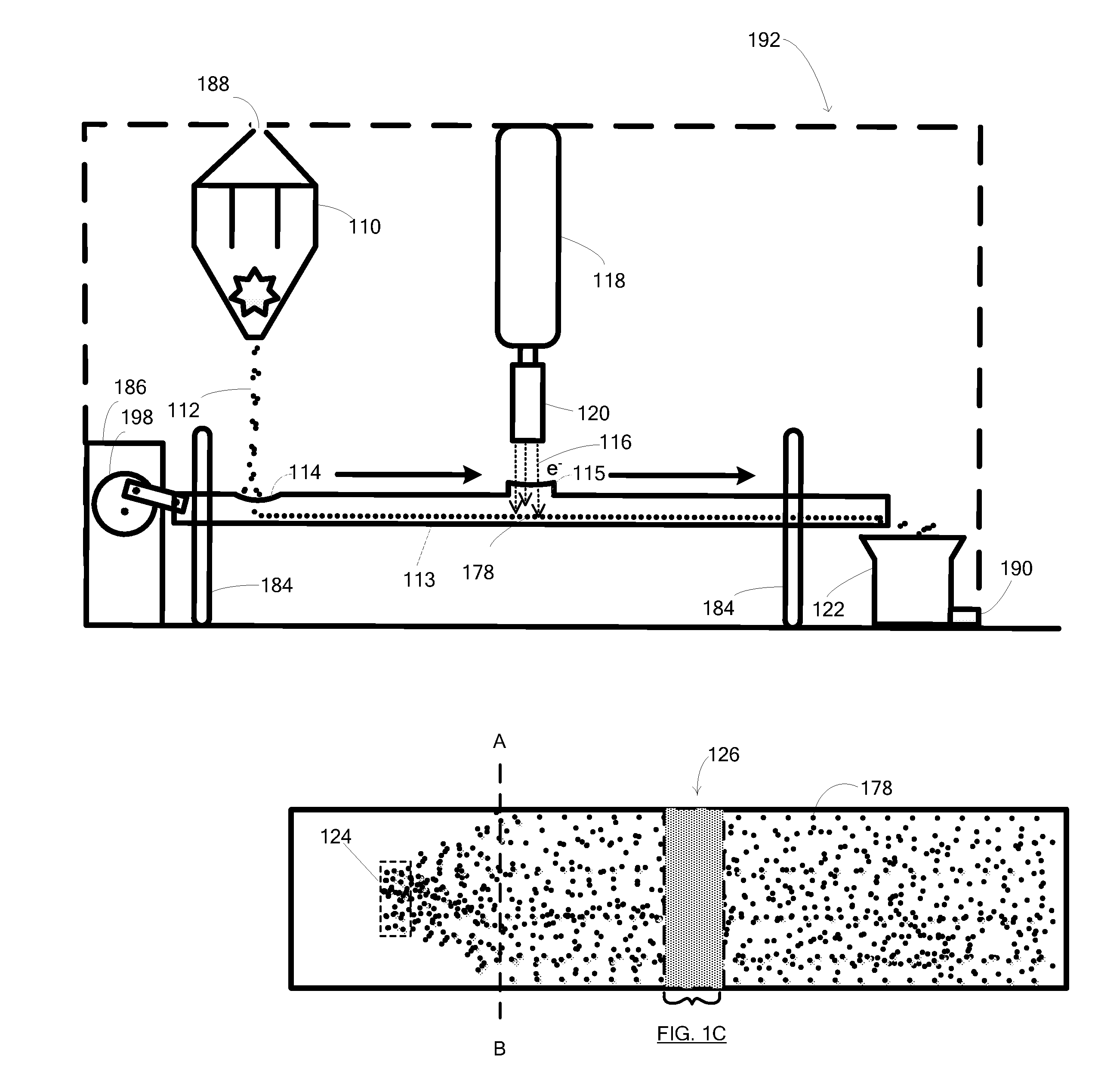
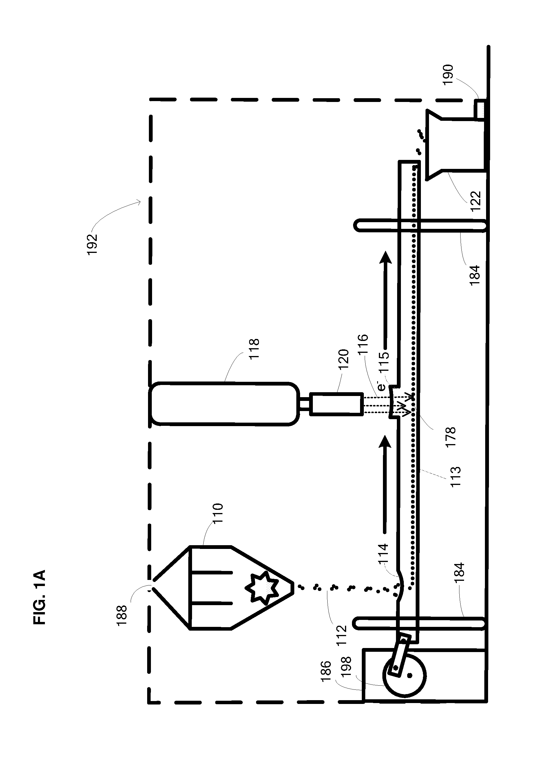
[0034]Provided herein are methods and apparatus for producing a treated biomass material with a vibratory conveyer. The methods and apparatus provide an advantage because the vibratory conveyor provides an efficient mode of conveying biomass material while it is under an irradiation source.

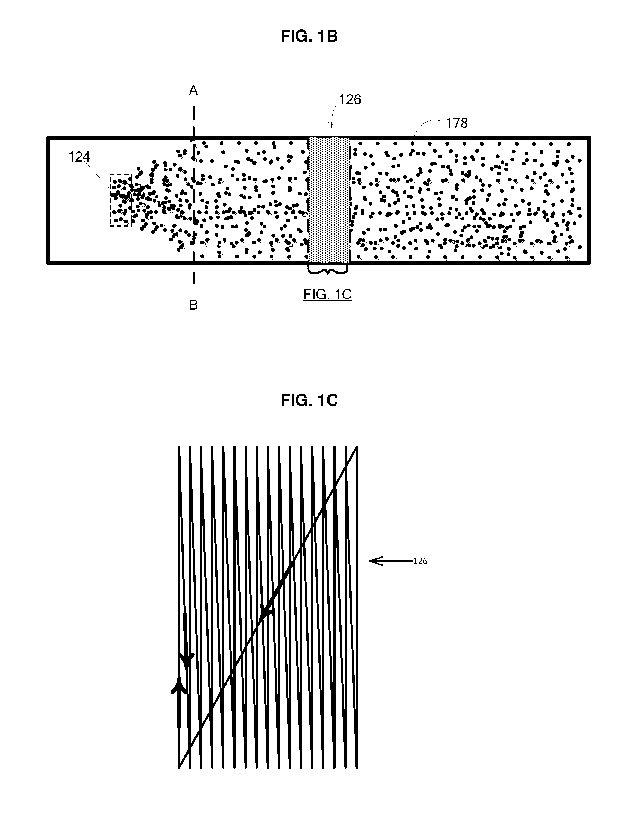
[0035]An exemplary embodiment is shown in FIGS. 1A-1E. FIG. 1A shows a front side view of a system for irradiation of particulate biomass. A spreader, for example, a distributer such as a CHRISTY SPREADER™110 containing a biomass drops a controlled stream of biomass 112 onto the trough of a covered vibratory conveyor 113 through an opening 114 in the cover of the conveyor. This aids in providing a substantially uniform thickness of the material spread across the conveyer. The covered vibratory conveyor is supported by a support 184 and includes a transverse vibration system including leaf springs. The transverse drive assembly 186 provides horizontal oscillating movement to the trough. The drive m...


PUM


Abstract

Methods and systems are described for processing cellulosic and lignocellulosic materials into useful intermediates and products, such as energy and fuels. For example, conveying systems and methods, such as highly efficient vibratory conveyors, are described for the processing of the cellulosic and lignocellulosic materials.

Description

CROSS REFERENCE TO RELATED APPLICATIONS[0001]This application is a continuation of PCT / US13 / 64289 filed Oct. 10, 2013, which claims priority to the following provisional applications: U.S. Ser. No. 61 / 711,807, filed Oct. 10, 2012; U.S. Ser. No. 61 / 711,801, filed Oct. 10, 2012; U.S. Ser. No. 61 / 774,684, filed Mar. 8, 2013; U.S. Ser. No. 61 / 774,773, filed Mar. 8, 2013; U.S. Ser. No. 61 / 774,731, filed Mar. 8, 2013; U.S. Ser. No. 61 / 774,735, filed Mar. 8, 2013; U.S. Ser. No. 61 / 774,740, filed Mar. 8, 2013; U.S. Ser. No. 61 / 774,744, filed Mar. 8, 2013; U.S. Ser. No. 61 / 774,746, filed Mar. 8, 2013; U.S. Ser. No. 61 / 774,750, filed Mar. 8, 2013; U.S. Ser. No. 61 / 774,752, filed Mar. 8, 2013; U.S. Ser. No. 61 / 774,754, filed Mar. 8, 2013; U.S. Ser. No. 61 / 774,775, filed Mar. 8, 2013; U.S. Ser. No. 61 / 774,780, filed Mar. 8, 2013; U.S. Ser. No. 61 / 774,761, filed Mar. 8, 2013; U.S. Ser. No. 61 / 774,723, filed Mar. 8, 2013; and U.S. Ser. No. 61 / 793,336, filed Mar. 15, 2013. The entire disclosure of...

Claims


Application Information

Patent Timeline
Patent Type & Authority Applications(United States)
IPC IPC(8): C13K13/00C13K1/02
CPCC13K13/002C13K1/02C08H8/00C10B19/00C10B53/02C10G1/02C10G32/04C10L5/442C10L5/445A61L2/087Y02E50/30Y02E50/10C10L2290/52C10L2290/36C10L2290/28C10L2290/24B01J19/082B01J19/085B01J19/12B01J19/123B01J19/125B01J19/22B65G27/04C10L5/403C10L5/46D21B1/02G21F3/00G21K5/04G21K5/10H01J5/18Y02P20/145B01J2219/0871B01J2219/0869B01J2219/0879B01J2219/1203B01J2219/12C10L2200/0469Y02P60/87H01J33/04H01J37/317H01J2237/202H01J37/20H01J2237/2002C12P7/10C12P2201/00
Inventor MEDOFF, MARSHALLMASTERMAN, THOMAS CRAIGPARADIS, ROBERT
Owner XYLECO INC
Why Eureka
Try Eureka