Headline sonar cable

a headline sonar cable and headline technology, applied in the field of cables, can solve the problems of adversely affecting trawl operation and fishing gear's performance, increasing the likelihood of data signal conductor damage of headline sonar cable, and weight of conventional steel headline sonar cable, so as to reduce the power required, the effect of splicing is easy and fas

Active Publication Date: 2014-08-07
HAMPIDJAN
View PDF5 Cites 12 Cited by
  • Summary
  • Abstract
  • Description
  • Claims
  • Application Information

AI Technical Summary

Benefits of technology

[0028]2. reduces the power required for trawler equipment that handles the cable.
[0029]Another advantage of the disclosed non-steel headline sonar cable is that it can be spliced more easily and more quickly than a conventional steel headline sonar cable.

Problems solved by technology

Surging significantly increases compressive force applied to the headline sonar cable at the winch thereby correspondingly increasing the likelihood that the headline sonar cable's data signal conductor may become damaged.
One disadvantage of a conventional steel headline sonar cable is its weight.
The weight of a steel headline sonar cable adversely affects trawl operation and fishing gear's performance.
Furthermore, a trawler's headline sonar cable winch frequently lacks sufficient power to tense the steel headline sonar cable since the winch is supporting the cable's weight.
Another disadvantage of a steel headline sonar cable occurs if the cable breaks.
A broken steel headline sonar cable, due to its weight, initially falls downward and then starts cutting through and damaging the trawl.
Similarly, when the trawler turns while towing a trawl it often becomes difficult to control a steel headline sonar cable to avoid contact between the cable and the trawl's warp lines and / or the bridles.
Contact between the headline sonar cable and the trawl's warp lines and / or bridles can damage either or both the headline sonar cable and the trawl's warp lines and / or bridles.
Contact between a headline sonar cable and a trawl's door can result either in the cable being cut, or the cable becoming entangled with the door so the trawl door become uncontrollable.
Over time rust also degrades a steel headline sonar cable.
Furthermore, steel headline sonar cables are difficult to splice because they typically consists of two twisted layers of steel wires, one layer twisted clockwise and the layer other counterclockwise.
If a conductor is placed inside or with a cable made from such a synthetic polymeric material it must be able to accept this elongation without either breaking or becoming brittle which ultimately results in premature conductor failure.
Consequently, none in the art have proposed a non-steel tension bearing data signal and energy cable capable of tolerating very high loads such as those applied to a trawl's headline sonar cable while also capable of being wound on a drum or winch under high tensions.
Past experiments at sheathing conductors (including fibre optic lines, copper wires, etc.) within strength members such as braided jacket layers formed of synthetic polymeric fibers have failed in high tension applications such as those described above.
Moreover, attempts to pre-stretch a strength member formed from synthetic polymeric fibers en-sheathing a conductor without breaking or otherwise causing failure of the conductor have also failed.
Using the metal central inner strength member to carry data signals doesn't work because during cable fabrication either the metallic wire either breaks or becomes so brittle as to fail prematurely.

Method used


Image

  • Headline sonar cable
  • Headline sonar cable
  • Headline sonar cable

Examples


Embodiment Construction

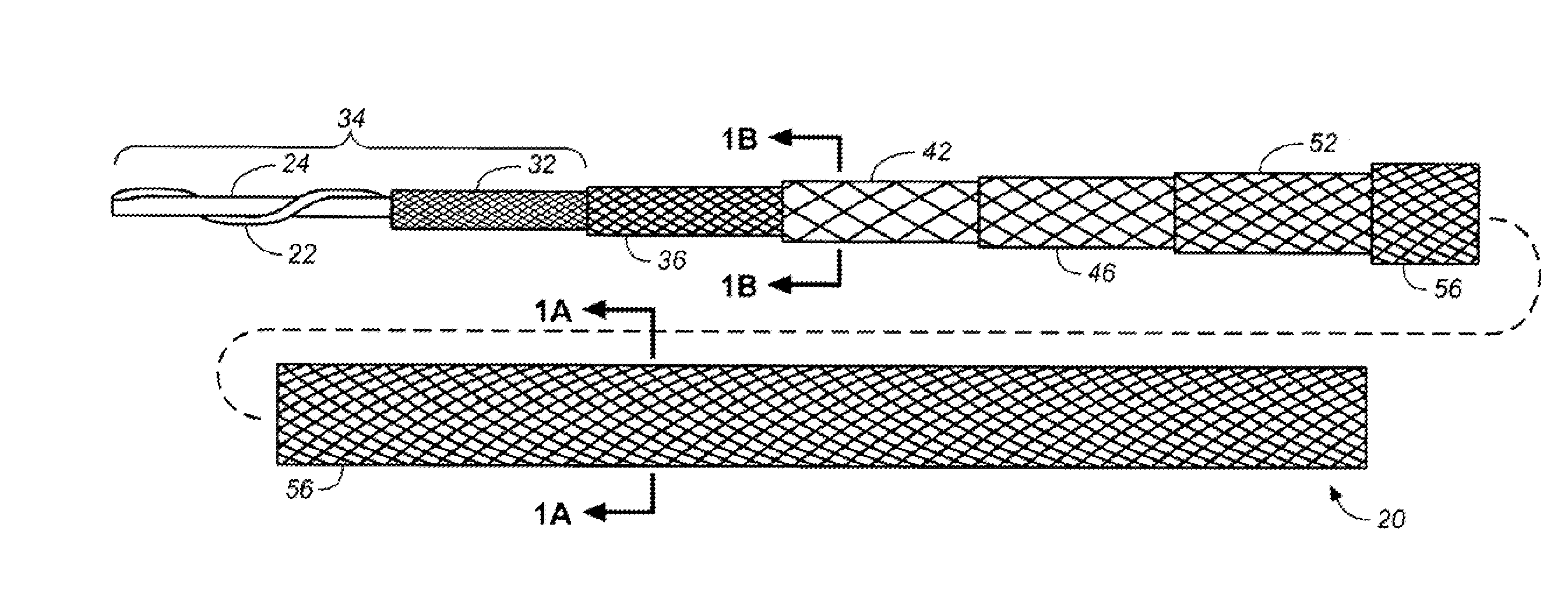
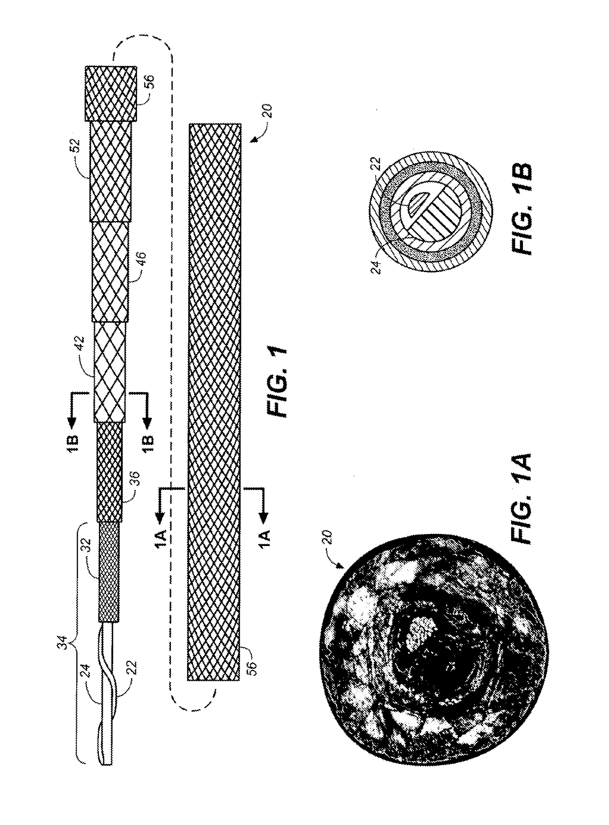
[0054]FIG. 1 illustrates a headline sonar cable in accordance with the present disclosure that is identified by the general reference character 20. FIG. 1 depicts a preferably insulated electrical conductor 22 wrapped around a rod 24 of deformable material and enclosed within a sequence of layers included in the particular embodiment of the headline sonar cable 20 illustrated in FIG. 1. The steps of a first fabrication method described below assemble the headline sonar cable 20 depicted in FIG. 1.

The First Fabrication Method

Step (1)

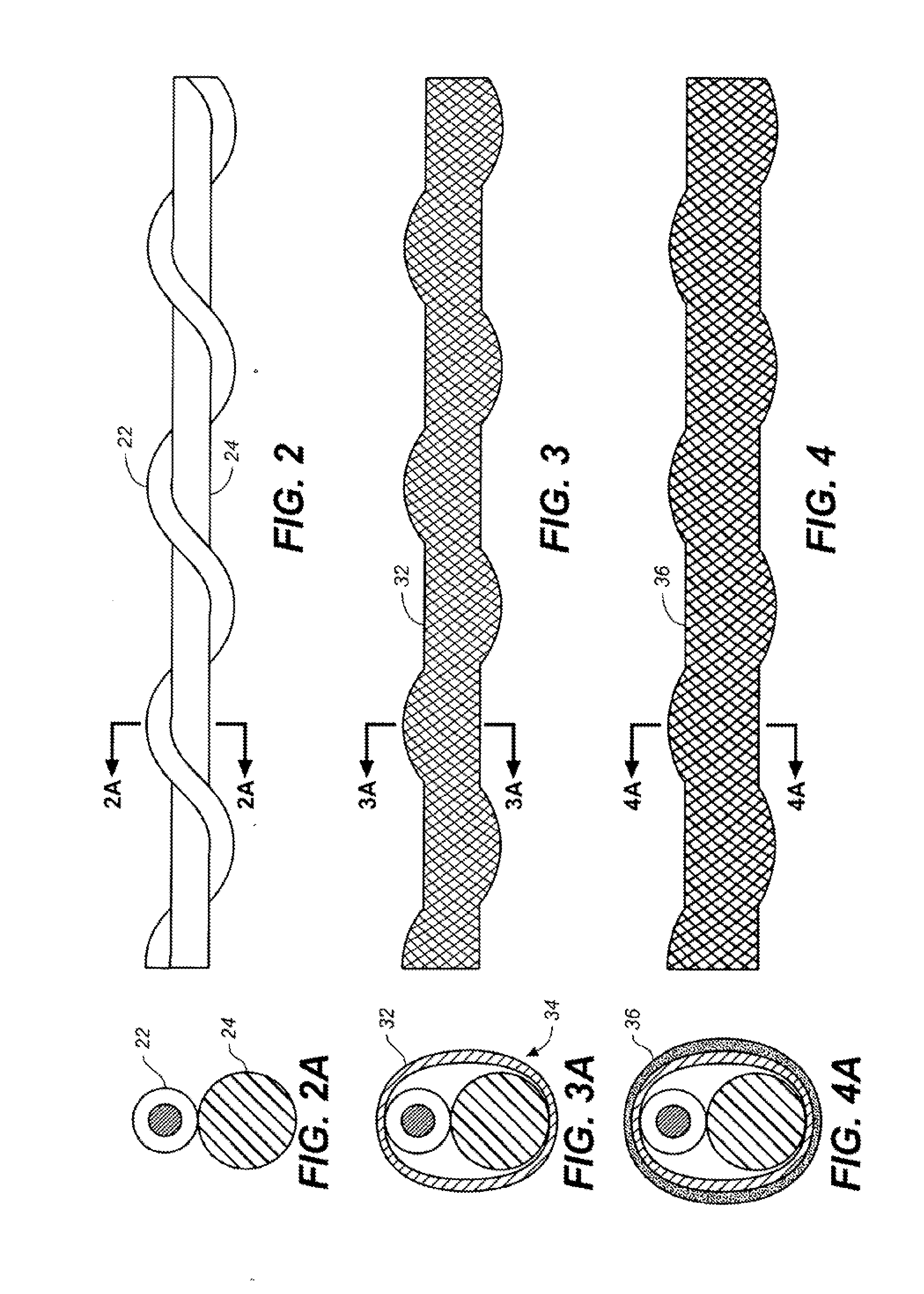
[0055]Fabrication of the headline sonar cable 20 depicted in FIG. 1 begins with twisting and / or wrapping the preferably insulated electrical conductor 22 around the rod 24 of deformable material as depicted in greater detail in FIGS. 2 and 2A. The deformable material of the rod 24 can be a thermoplastic material, a plastic material, or any other material that deforms when exposed to pressures generated while stretching various layers of the headline sonar...


PUM

PropertyMeasurementUnit
temperaturesaaaaaaaaaa
temperatureaaaaaaaaaa

Abstract

A production method for a headline sonar cable (20, 120) that exhibits a high breaking-strength and lighter weight than a conventional steel headline sonar cable. Producing the headline sonar cable (20, 120) is characterized by the steps of:
    • a. providing an elongatable internally-located conductive structure (34, 134) that is adapted for data signal transmission; and
    • b. braiding a strength-member jacket layer (52) of polymeric material around the structure (34, 134) while ensuring that the structure (34, 134) is slack when surrounded by the jacket layer (52).
The structure (34, 134) of the cable (20, 120) retains conductivity upon stretching of the jacket layer (52) surrounding the structure (34, 134) that lengthens the cable (20, 120). For one embodiment of the method a conductor (20) wrapped around a rod (24) and enclosed within a sheath layer (32) forms the structure (34, 134). For another embodiment of the method a braided conductor (122) enclosed within a braided sheath (124) and a polymeric layer (132) forms the structure (34, 134).

Description

TECHNICAL FIELD[0001]The present disclosure relates generally to the technical field of cables and, more particularly, to a cable that is made from a synthetic polymeric material, that has cross-sectional symmetry, that exhibits high stiffness and breaking strength, and that includes data signal and / or energy conductors therein.BACKGROUND ART[0002]A towed trawl usually includes a headline sonar sensor for monitoring the trawl's headline height, the trawl's opening and fish schools in front of the trawl. A data transmission cable, i.e. a headline sonar cable that is sometimes called a third wire includes a conductor for transferring data signals from the headline sonar sensor to the towing vessel. Presently, strength members of conventional headline sonar cables are made from steel, and enclose a central copper conductor that is surrounded by layed, multi-layed and torsion balanced, or braided copper wires. The braided copper wires surrounding the central conductor shield the data si...

Claims


Application Information

Patent Timeline
Patent Type & Authority Applications(United States)
IPC IPC(8): H01B13/06H01B7/14
CPCH01B7/14H01B13/06H01B13/22H01B7/045G01V2001/204D07B1/147D07B5/12Y10T29/49117G01V1/201Y10T29/49119H01B7/145H01B7/0208H01B7/0266H01B13/0006H01B13/2606H01B13/2626H01B13/32H01B11/22
Inventor ERLENDSSON, HJORTUR
Owner HAMPIDJAN
Why Eureka
Try Eureka