Internal combustion engine coupled turbocharger with an infinitely variable transmission

a technology of transmission and internal combustion engine, which is applied in the direction of machines/engines, mechanical equipment, etc., can solve the problems of limited air volume, affecting the efficiency of internal combustion engine, so as to reduce the turbo lag, reduce the boost threshold of the turbocharger, and increase the efficiency of the internal combustion engine

Inactive Publication Date: 2014-08-14
DANA CORP
View PDF2 Cites 34 Cited by
  • Summary
  • Abstract
  • Description
  • Claims
  • Application Information

AI Technical Summary

Benefits of technology

[0011]Presently provided by the invention, a turbocharger for an internal combustion engine that is simply controlled, reduces turbo lag, dec

Problems solved by technology

The volumetric efficiency, which is the amount of air inducted into the engine cylinder by the piston divided by the cylinder volume, is limited both by the atmospheric pressure and the change in pressure needed to bring air into the cylinder.
Due to inherent limitations in the design, the turbocharger 100 is subject to several issues that may be solved by using a complex control methodology or through the addition of costly technologies to the turbocharger 100.
One issue associated with such a turbocharger is a maximum boost pressure that the engine can withstand without damage to components of the engine due to increased pressure.
Further, knocking of the engine may damage the turbocharger.
The wastegate diverts a portion of the exhaust gas from the turbine, thus limiting the pressure and amount of energy that can be recuperated by the turbine.
In a conventional configuration of a turbocharger, the excessive wasted exhaust and the complex control of the wastegate cannot be avoided.
Another issue associated with such a turbocharger issue is a dynamic known as turbo lag.
Turbo lag is caused

Method used


Image

  • Internal combustion engine coupled turbocharger with an infinitely variable transmission
  • Internal combustion engine coupled turbocharger with an infinitely variable transmission
  • Internal combustion engine coupled turbocharger with an infinitely variable transmission

Examples


Embodiment Construction

[0025]It is to be understood that the invention may assume various alternative orientations and step sequences, except where expressly specified to the contrary. It is also to be understood that the specific devices and processes illustrated in the attached drawings, and described in the following specification are simply exemplary embodiments of the inventive concepts defined herein. Hence, specific dimensions, directions or other physical characteristics relating to the embodiments disclosed are not to be considered as limiting, unless expressly stated otherwise.

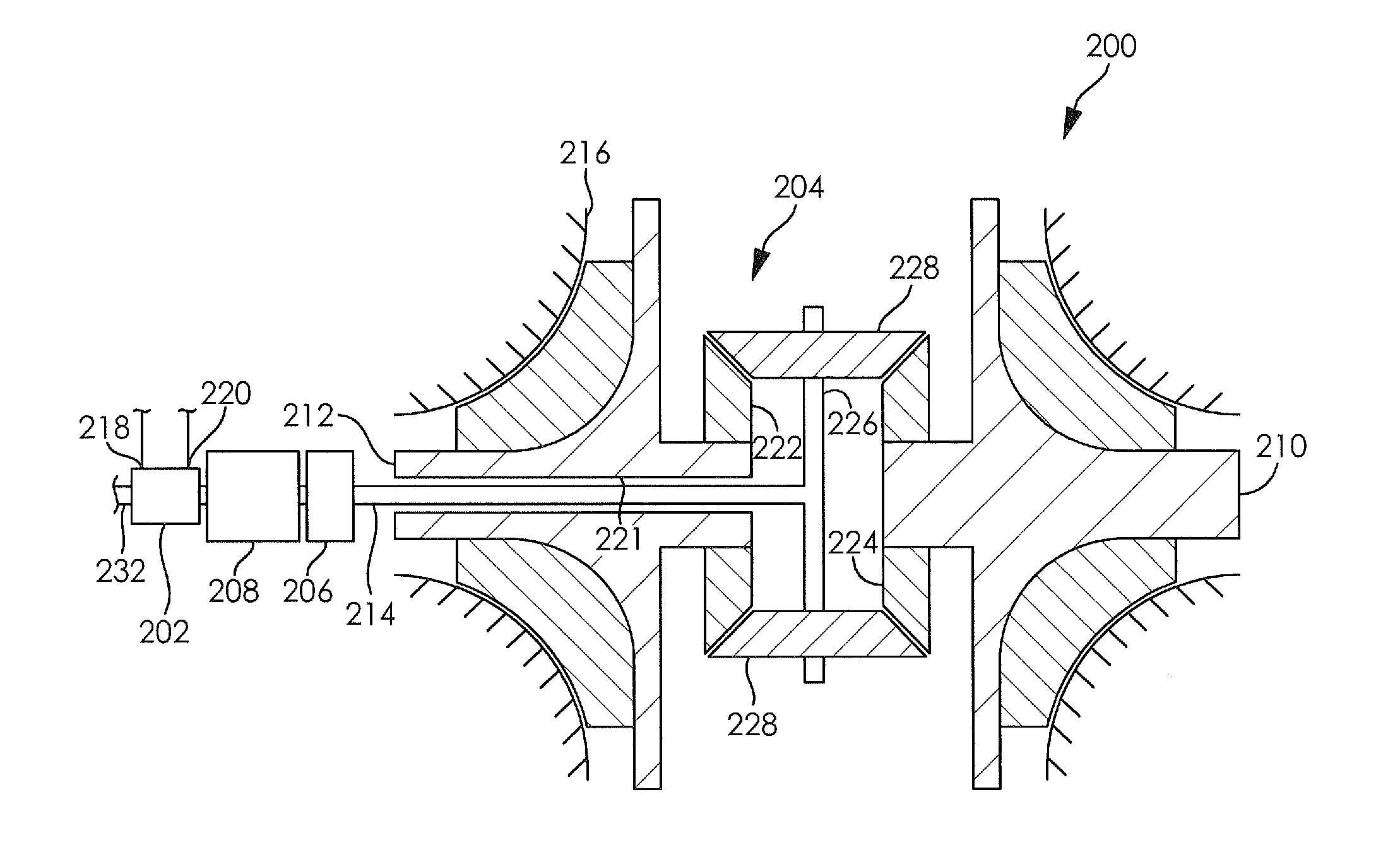
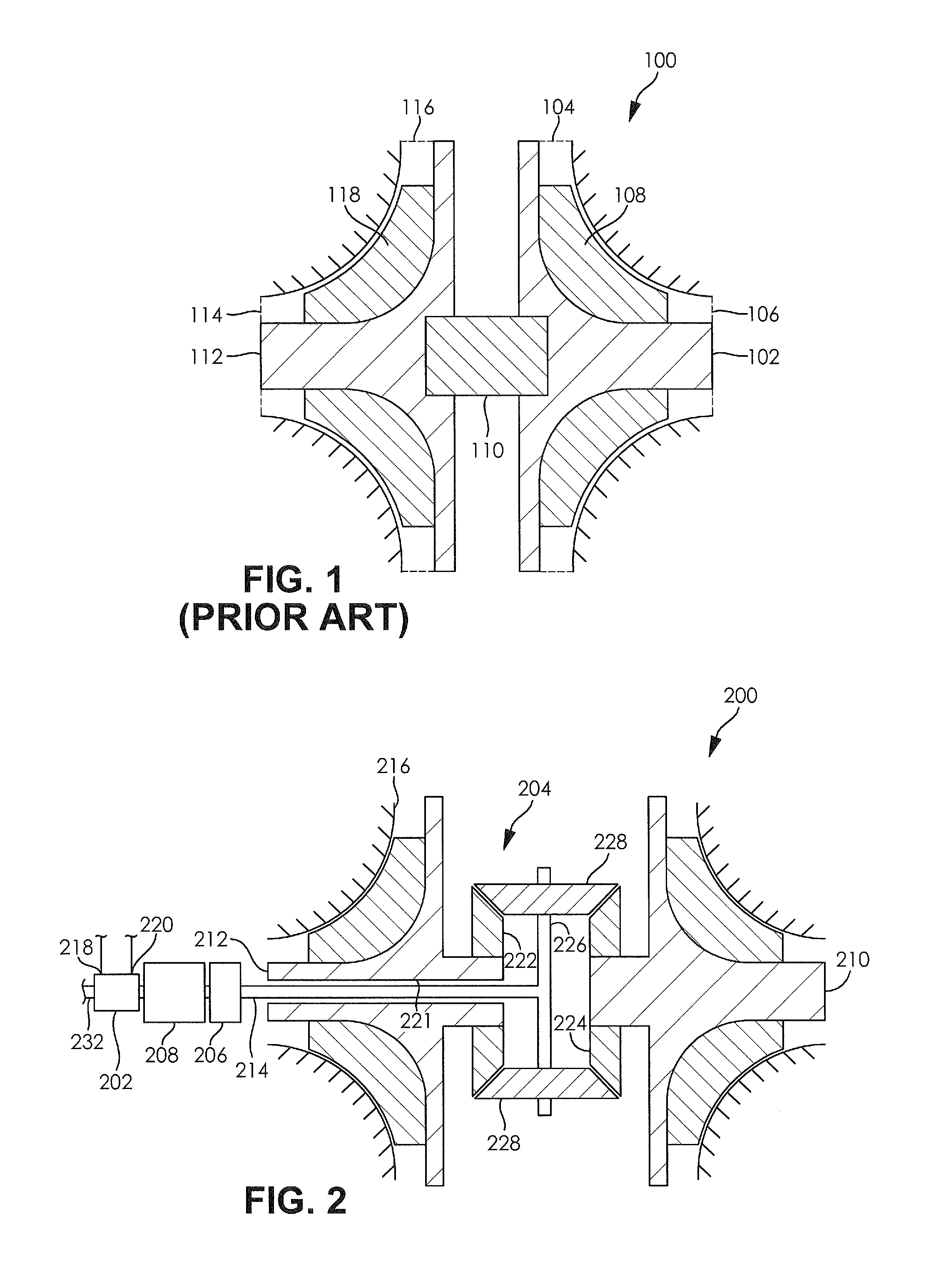
[0026]FIG. 2 schematically illustrates a turbocharger 200 for use with an internal combustion engine 202. The turbocharger 200 is in driving engagement and fluid communication with the internal combustion engine 202. The turbocharger 200 is in driving engagement with the internal combustion engine 202 through a differential device 204, a ratio adjusting device 206, and an infinitely variable transmission 208. Typically, th...


PUM


Abstract

A turbocharger for use with an internal combustion engine is provided. The turbocharger comprises a differential device having a carrier portion, a compressor portion, and a turbine portion. The compressor portion is in driving engagement with a first portion of the differential device. The turbine portion is in driving engagement with a second portion of the differential device. The carrier portion of the differential device is in driving engagement with an infinitely variable transmission. The infinitely variable transmission is in driving engagement with the internal combustion engine. The turbocharger is simply controlled, reduces turbo lag, decreases a boost threshold of the turbocharger, and increases an efficiency of the internal combustion engine.

Description

CLAIM OF PRIORITY[0001]The present application claims the benefit of priority to U.S. Provisional Application No. 61 / 762,379 filed on Feb. 8, 2013, which is incorporated herein in its entirety by reference.FIELD OF THE INVENTION[0002]The present invention relates to energy recovery systems and more specifically to waste heat recovery systems used with internal combustions engines.BACKGROUND OF THE INVENTION[0003]In conventional reciprocating piston engines, ambient air is typically pulled inside an engine cylinder during an intake (or induction) stroke of a piston. The volumetric efficiency, which is the amount of air inducted into the engine cylinder by the piston divided by the cylinder volume, is limited both by the atmospheric pressure and the change in pressure needed to bring air into the cylinder. Increasing the volumetric efficiency reduces relative engine losses, increases engine efficiency, and also increase the power output of the engine without increasing a displacement ...

Claims


Application Information

Patent Timeline
IPC IPC(8): F02B37/04
CPCF02B37/04F02B37/105F02B39/04F02B41/10F02C3/113F02C6/12F02C7/36F04D25/026F04D25/028F05D2220/40F16H15/28G06F8/65H02K49/102Y02T10/12F16H15/40F16H48/08H02K49/10
Inventor VERSTEYHE, MARK RJDUCHENE, THIBAUT E.BYLTIAUW, MATTHIAS WJREMBROSKI, DONALD J.
Owner DANA CORP
Why Eureka
Try Eureka