Apparatus And Method For Volume And Mass Estimation Of A Multiphase Fluid Stored At Cryogenic Temperatures

Active Publication Date: 2014-08-14
WESTPORT FUEL SYST CANADA INC
View PDF12 Cites 26 Cited by
  • Summary
  • Abstract
  • Description
  • Claims
  • Application Information

AI Technical Summary

Benefits of technology

[0019]An improved method estimates fluid mass in a cryogenic tank that holds a multiphase fluid comprising a liquid and a vapor. The method comprises steps of determining a level of the liquid in the cryogenic tank, calculating a first volume of the liquid from inputs comprising the level of the liquid, measuring vapor pressure inside the tank, and calculating a first mass of the liquid from inputs comprising the first volume and the vapor pressure. The method further comprises a step of estimating a fuelling range for a vehicle based on the first mass when the fluid is a fuel for combustion in an internal combustion engine in the vehicle. When the step of determining the level of the liquid employs a capacitance-type level sensor, the method comprises sub-steps of providing a pair of spaced apart conductors that are disposed within the cryogenic tank and form in part a capacitor; and calibrating the capacitance-type level sensor at least once prior to first introduction of the cryogenic liquid in the cryogenic tank. The step of calibrating comprises steps of applying a measuring signal to the capacitor; measuring a first parameter representative of a first capacitance of the capacitor in a dry state where a first dielectric with a first dielectric constant is disposed between the spaced apart conductors in the dry state; estimating a second parameter representative of an empty level in the cryogenic tank where a second dielectric with a second dielectric constant is disposed between the spaced apart conductors at the empty level and the second parameter is estimated based on the first parameter and a first ratio of dielectric constants comprising the first dielectric constant and the second dielectric constant; and estimating a third parameter representative of a full level in the cryogenic tank where a third dielectric with a third dielectric constant is disposed between the spaced apart conductors at the full level and the third parameter is estimated based on the first parameter and a second ratio of dielectric constants comprising the first dielectric constant and the third dielectric constant. The second dielectric is the vapor and the third dielectric is the liquid. The second dielectric constant and the third dielectric constant can be determined as a function of the vapor pressure. When employing the capacitance-type level sensor the step of determining the level comprises sub-steps of applying the measuring signal to the capacitor; measuring a fourth parameter representative of the level of the liquid in the cryogenic tank; and calculating the level from inputs comprising the second parameter, the third parameter, the empty level, the full level and the fourth parameter. The calculation can be done by interpolating the level between the empty level and the full level based on the fourth parameter. The first volume can be calculated by employing a mathematical relationship between the level and the first volume or an empirical relationship between the level and the first volume. The first mass can be calculated by estimating the density of the liquid from inputs comprising the vapor pressure and calculating the first mass from inputs comprising the density and the first volume. The density can be estimated by employing a mathematical relationship between the vapor pressure and the density, or by employing an empirical relationship between the vapor pressure and the density. For example, the density can be estimated from inputs comprising a speed of propagation of acoustic waves through the liquid, or the density can be estimated based on the composition of the liquid. When the liquid is natural gas the composition can be estimated based on the percentage composition of methane. The method can further comprise a step of calculating a second mass of the vapor where a total fluid mass is the sum of the first mass and the second mass. The total fluid mass can be employed to estimate fuelling range for a vehicle when the fluid is a fuel for combustion in an internal combustion engine of a vehicle. The second mass can be calculated based on steps comprising calculating a second volume occupied by the vapor, estimating a density of the vapor, and estimating the second mass based on the second volume and the density. The density of the vapor can be determined based on the vapor pressure and the vapor composition.
[0020]An improved apparatus is provided for estimating fluid mass in a cryogenic tank that holds a multiphase fluid comprising a liquid and a vapor. The apparatus comprises a level sensor, a pressure sensor and a computer. The level sensor provides a parameter representative of a level of the liquid. The pressure sensor provides a pressure signal representative of vapor pressure inside the cryogenic tank. The computer is operatively connected with the level sensor and the pressure sensor to receive the parameter and the pressure signal. The computer is programmed to determine the level from inputs comprising the parameter,

Problems solved by technology

However, accurately measuring the liquid level of a cryogenic liquid held in a storage tank is still a challenging application.
It can be especially challenging to accurately measure liquid level of cryogenic liquids in storage tanks that are mobile, such as vehicular fuel tanks storing LNG.
Accurately detecting the level of liquid remaining for vehicular fuel tank applications is important because the consequence of an inaccurate level measurement can result in a vehicle being stranded if it runs out of fuel, or reduced operational efficiency if the vehicle is re-fuelled more frequently than necessary.
In addition, for vehicles that use a high pressure pump to deliver the fuel to the engine, there can be accelerated wear of the pump components if the pump is operated frequently when the fuel tank is empty.
One of the challenges of LNG is that, in many applications, once delivered into the storage tank, it needs extra space in which to expand when the LNG warms.
Excessive heat leakage into a cryogenic tank, as well as causing the LNG itself to expand, will cause the cryogenic liquid to boil.
Eventually, with continued heat leakage, LNG will boil or evaporate resulting in a pressure build up in the storage tank.
One problem with use of the ullage space

Method used


Image

  • Apparatus And Method For Volume And Mass Estimation Of A Multiphase Fluid Stored At Cryogenic Temperatures
  • Apparatus And Method For Volume And Mass Estimation Of A Multiphase Fluid Stored At Cryogenic Temperatures
  • Apparatus And Method For Volume And Mass Estimation Of A Multiphase Fluid Stored At Cryogenic Temperatures

Examples


Embodiment Construction

)

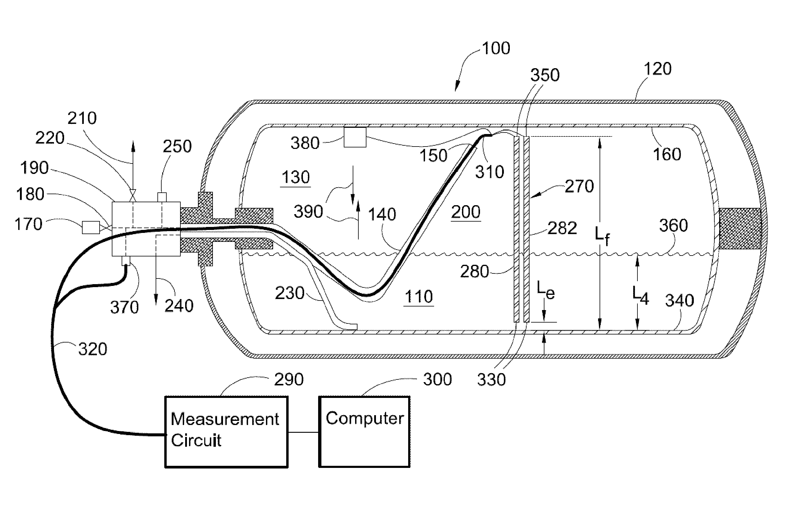
[0026]Referring to the figures and first to the illustrated embodiment of FIG. 1, there is shown an apparatus 100 for estimating a volume and a mass of a cryogenic liquid 110 in cryogenic storage tank 120. Cryogenic space 130 is filled by introducing cryogenic fluid through conduit 140 comprising open end 150 disposed near top 160. Cryogenic fluid can be introduced into conduit 140 through coupling 170 which is located outside tank 120. Coupling 170 can comprise shut off valve 180 that opens when coupled to a fill nozzle, and closes when the fill nozzle is not coupled to coupling 170.

[0027]Manifold block 190 can be used to reduce the number of fittings and connections to simplify assembly and reduce the number of potential leak points. Internal passages within manifold block 190 connect the conduits that extend into the interior of tank 120 with at least four outside connections. As previously indicated, one internal passage leads from conduit 140 to coupling 170 for filling cryoge...


PUM


Abstract

An apparatus and method estimate fluid mass in a cryogenic tank that holds a multiphase fluid comprising a liquid and a vapor. The apparatus comprises a level sensor, a pressure sensor and a computer. The level sensor provides a parameter representative of a level of the liquid. The pressure sensor provides a pressure signal representative of vapor pressure inside the cryogenic tank. The computer is operatively connected with the level sensor and the pressure sensor to receive the parameter and the pressure signal, and is programmed to determine the level from inputs comprising the parameter, to calculate a first volume of the liquid from inputs comprising the level, and to calculate a first mass of the liquid from inputs comprising the first volume and the pressure signal.

Description

CROSS-REFERENCE TO RELATED APPLICATIONS[0001]This application is a continuation of International Application No. PCT / CA2012 / 050628 having an international filing date of Sep. 11, 2012 entitled “Apparatus And Method For Volume And Mass Estimation Of A Multiphase Fluid Stored At Cryogenic Temperatures”. The '628 international application claimed priority benefits, in turn, from Canadian Patent Application No. 2,753,588 filed on Sep. 27, 2011. The '628 international application is hereby incorporated by reference herein in its entirety.FIELD OF THE INVENTION[0002]An apparatus and method estimate a volume and a mass of a multiphase fluid stored at cryogenic temperatures in a vessel. When the multiphase fluid is a fuel consumed by a vehicle, the apparatus and method can be used to estimate vehicle range.BACKGROUND OF THE INVENTION[0003]The employment of alternative fuels such as liquefied natural gas (LNG) to power automotive vehicles has provided advantages that are both economical and ...

Claims


Application Information

Patent Timeline
IPC IPC(8): G01F25/00
CPCG01F23/30G01F25/00G01N9/24G01F23/14G01F23/26G01F23/296G01F23/0061G01F25/0084G01F17/00F17C13/021F17C2201/0109F17C2201/035F17C2201/056F17C2201/058F17C2203/0629F17C2205/0332F17C2221/011F17C2221/012F17C2221/014F17C2221/016F17C2221/033F17C2223/0161F17C2223/033F17C2223/047F17C2225/045F17C2250/032F17C2250/0417F17C2250/0421F17C2250/043F17C2250/0473F17C2250/0495F17C2260/025F17C2260/026F17C2270/0168Y02E60/32G01F23/80
Inventor HARPER, GREGORY C.BATENBURG, GREGORY A.SCHRANZ, PAUL S.
Owner WESTPORT FUEL SYST CANADA INC
Why Eureka
Try Eureka