Direct injection fuel pump

a fuel pump and direct injection technology, applied in the direction of fuel injecting pumps, machines/engines, electric control, etc., can solve the problems of high pressure pump deformation, pump degradation, fuel injection may cease during the operation mode, etc., to improve the lubrication of fuel pump, and reduce the degradation rate of fuel pump

Active Publication Date: 2014-08-14
FORD GLOBAL TECH LLC
View PDF26 Cites 42 Cited by
  • Summary
  • Abstract
  • Description
  • Claims
  • Application Information

AI Technical Summary

Benefits of technology

[0004]By regulating pressure in the compression chamber of a direct injection fuel pump it may be possible to lubricate the direct injection fuel pump's cylinder and piston when flow out of the direct injection fuel pump to fuel injectors is stopped. Specifically, a fuel pressure differential across the direct injection fuel pump's piston may be provided that allows fuel to flow into the piston/bore clearance and lubricate an area. Further, pressure in the compression chamber is less than pressure in the fuel rail so there is no flow from the direct injection fuel pump to the fuel rail. In this way, the piston may continue to reciprocate within the direct injection fuel pump with a low rate of degradation and without supplying fuel to the engine.
[0005]The present description may provide several advantages. Specifically, the approach may improve fuel pump lubrication and reduce fuel pump degradation. Additionally, pressure in the compression chamber can be regulated to a higher pressure than low pressure fuel pump pressure so that engine operation may be

Problems solved by technology

However, if the engine is supplied fuel via direct fuel injectors and a high pressure fuel pump, the high pressure pump may degrade when fuel flow through the high pressure pump is stopped while the fuel injectors are deactivated.
Specifically, the lub

Method used


Image

  • Direct injection fuel pump
  • Direct injection fuel pump
  • Direct injection fuel pump

Examples


Embodiment Construction

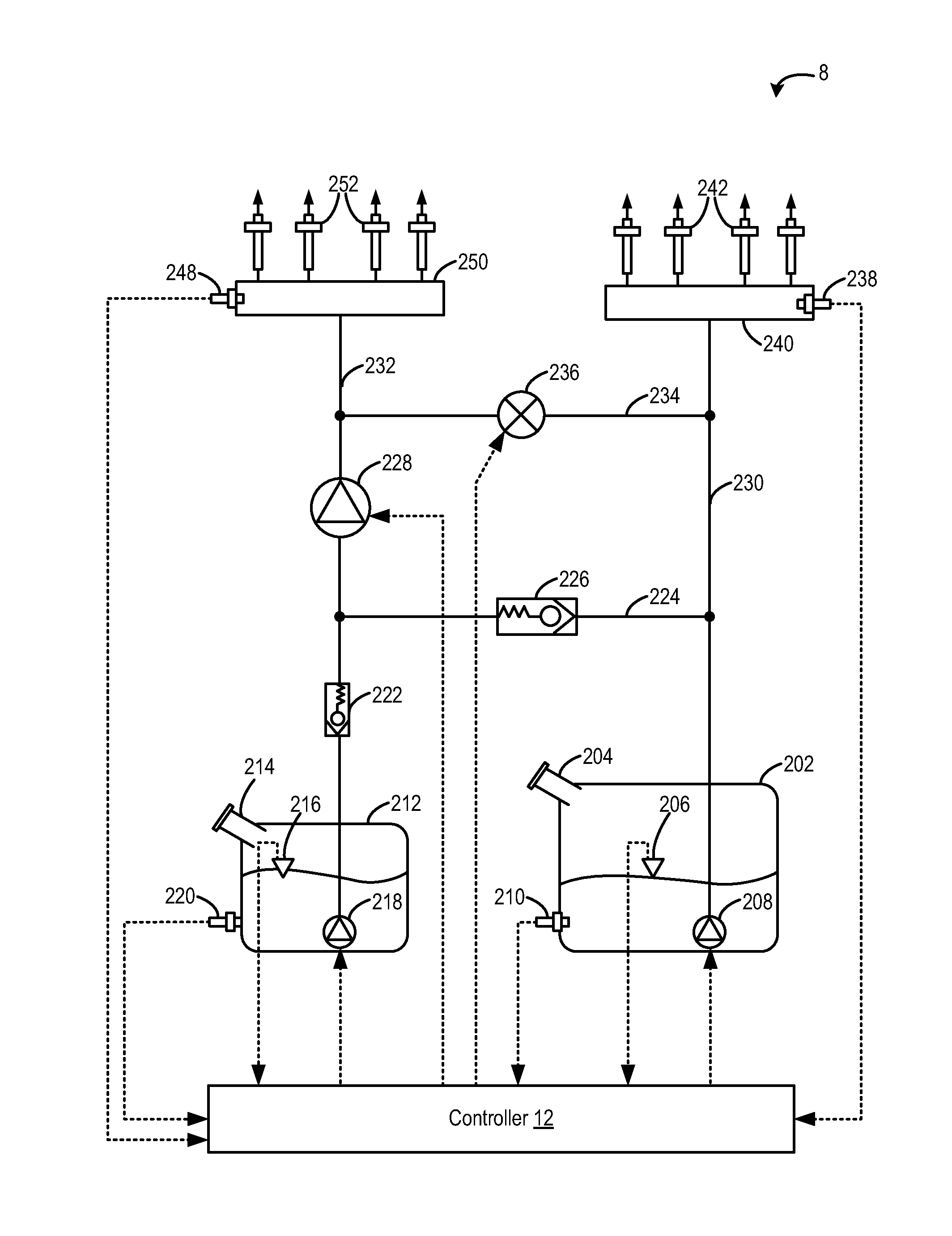
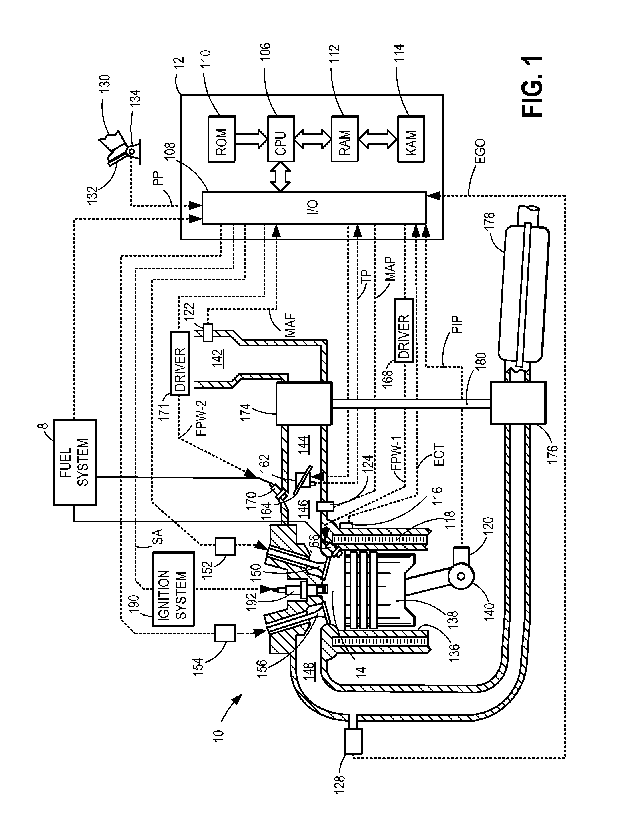
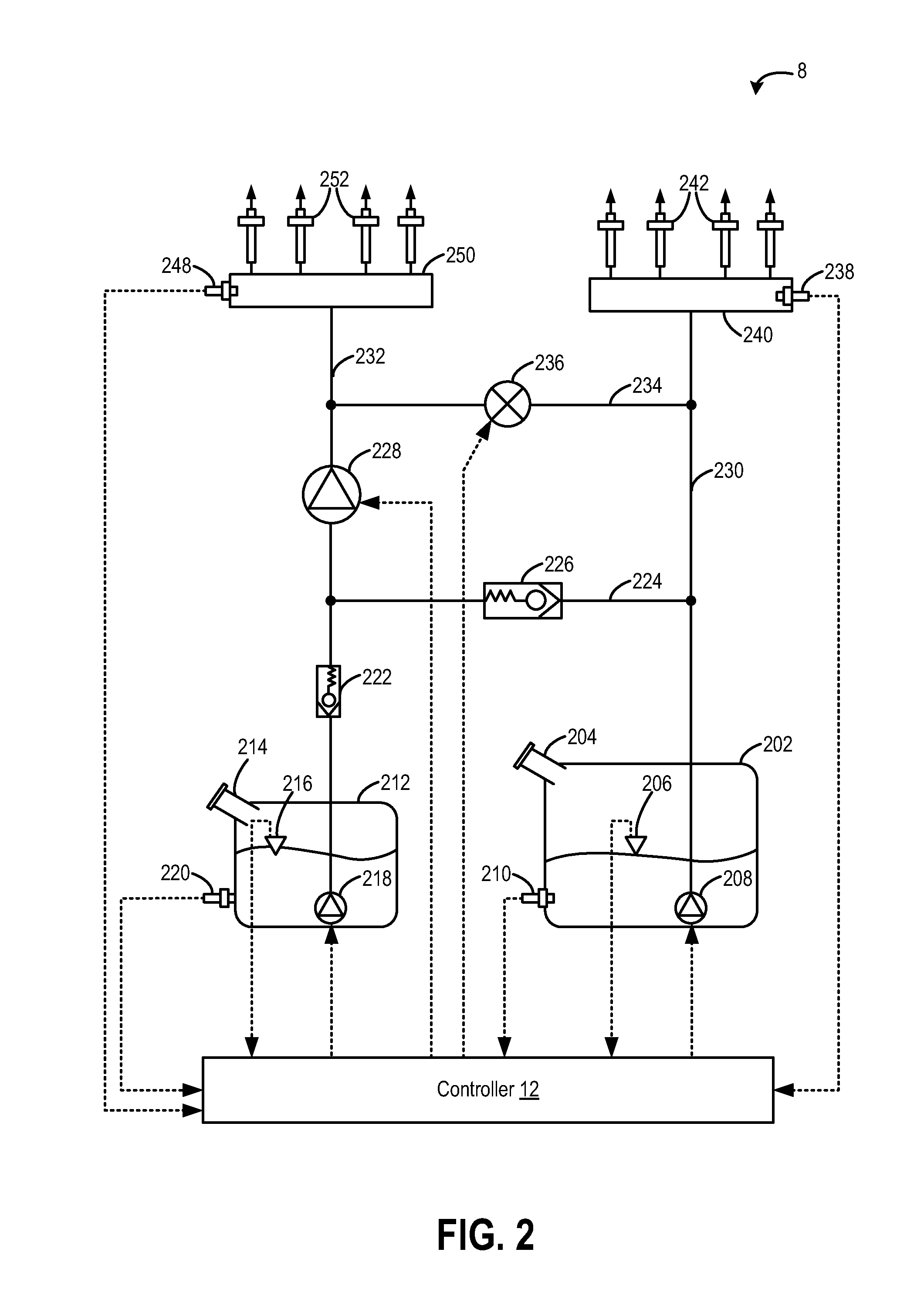
[0021]The following disclosure relates to methods and systems for operating a direct injection (high pressure, HP) fuel pump, such as the system of FIGS. 2 and 3. The fuel system may be configured to deliver one or more different fuel types to a combustion engine, such as the engine of FIG. 1. Alternatively, the fuel system may supply a single type of fuel as shown in the system of FIG. 3. A direct injection fuel pump with integrated pressure relief and check valves as shown in FIG. 4 may be incorporated into the systems of FIGS. 2 and 3. Alternatively, the pressure relief valves and check valves may be external to the direct injection fuel pump. In some examples, the direct injection fuel pump may further include an accumulator as shown in FIG. 5A to further enhance direct injection fuel pump operation. A variety of graphs may exist for different pre-pressurizations of the accumulator, where the associated pressure-volume diagram of which is shown in FIG. 5B. The direct injection f...


PUM


Abstract

Methods and systems are provided for a direct injection fuel pump. The methods and system control pressure within a compression chamber so as to improve fuel pump lubrication.

Description

CROSS REFERENCE TO RELATED APPLICATIONS[0001]The present application is a continuation-in-part of U.S. patent application Ser. No. 13 / 830,022, “DIRECT INJECTION FUEL PUMP,” filed on Mar. 14, 2013, which claims priority to U.S. Provisional Patent Application No. 61 / 763,881, “DIRECT INJECTION FUEL PUMP,” filed on Feb. 12, 2013, the entire contents of each of which are incorporated herein by reference for all purposes.BACKGROUND AND SUMMARY[0002]A vehicle's fuel systems may supply fuel to an engine in varying amounts during the course of vehicle operation. During some conditions, fuel is not injected to the engine but fuel pressure in a fuel rail supplying fuel to the engine is maintained so that fuel injection can be reinitiated. For example, during vehicle deceleration fuel flow to one or more engine cylinders may be stopped by deactivating fuel injectors. If the engine torque demand is increased after fuel flow to the one or more cylinders ceases, fuel injection is reactivated and t...

Claims


Application Information

Patent Timeline
IPC IPC(8): F02M59/38
CPCF02M59/38F02M2200/40F02M63/0265F02M63/0001F02M59/367F02M2200/03F02M2200/09F02M2200/02F02D41/3094F02D41/3845F02D2041/3881F02M59/102
Inventor PURSIFULL, ROSS DYKSTRAULREY, JOSEPH NORMANLAWTHER, ROBIN IVOZENG, PAUL
Owner FORD GLOBAL TECH LLC
Why Eureka
Try Eureka