Driving method of electrochemical device

a technology of electrochemical devices and driving methods, which is applied in the direction of electric vehicles, charging/discharging of charge maintainance, transportation and packaging, etc., can solve the problems of clogging and alteration of the separation between the positive electrode and the negative electrode, and achieve the reduction of fire risk, increase internal resistance, and increase the effect of capacity

Active Publication Date: 2014-08-14
SEMICON ENERGY LAB CO LTD
View PDF3 Cites 8 Cited by
  • Summary
  • Abstract
  • Description
  • Claims
  • Application Information

AI Technical Summary

Benefits of technology

[0029]When reverse pulse current is supplied multiple times during charge, a separator is prevented from being clogged and a voltage increase (increase in internal resistance) during charge is suppressed, so that charge can be normally performed repeatedly. Further, supply of reverse pulse current during charge can suppress a reduction in capacity and reduce a risk of fire. Furthermore, a battery whose capacity is reduced from an initial value because of rapid charge can recover from degradation by reverse pulse current supplied multiple times during charge.

Problems solved by technology

When a battery that deteriorated because of the capacity decrease was analyzed, it was found that a separator provided between a pair of electrodes (a positive electrode and a negative electrode) was altered and clogged.

Method used


Image

  • Driving method of electrochemical device
  • Driving method of electrochemical device
  • Driving method of electrochemical device

Examples


embodiment 1

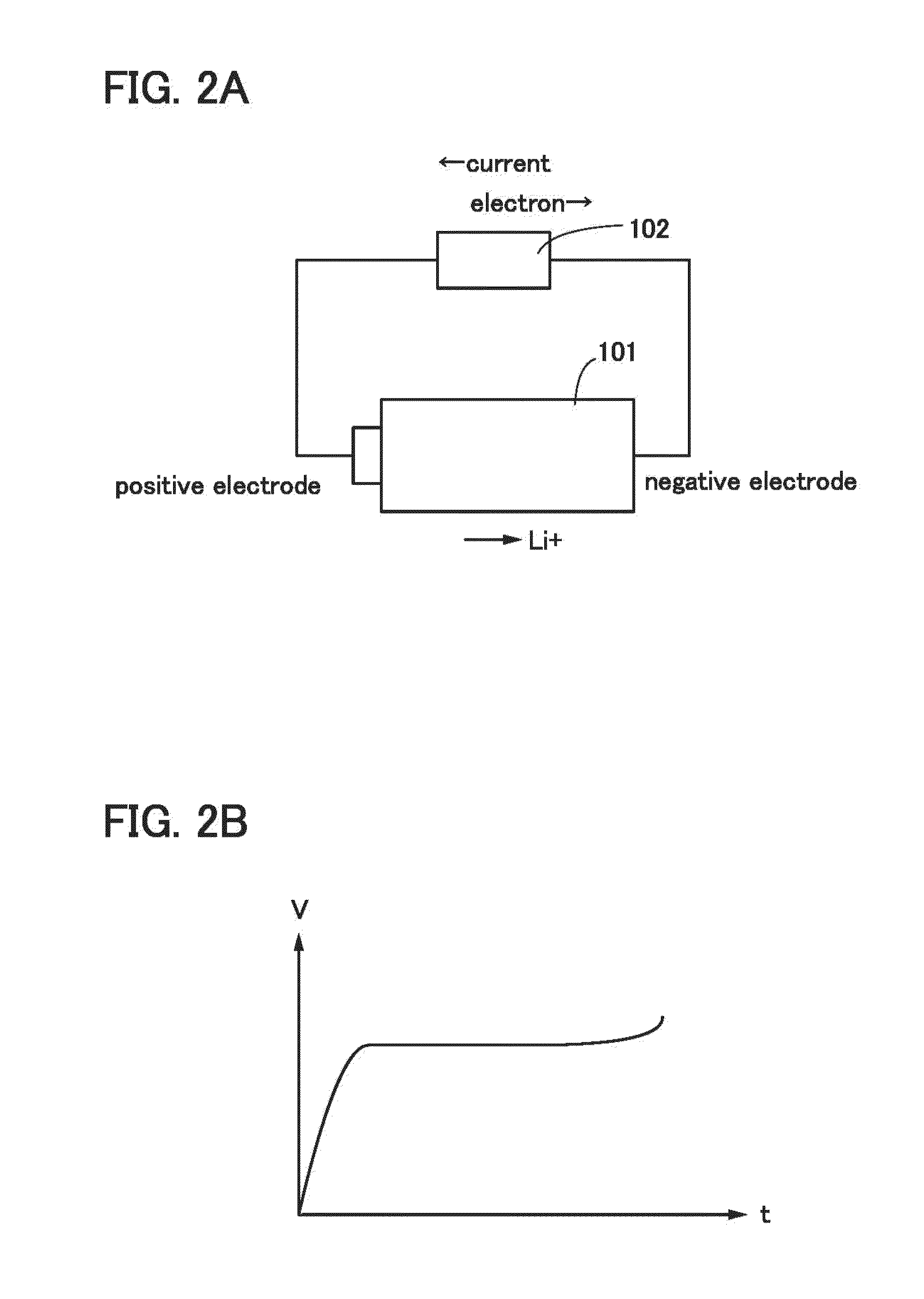
[0045]First, description is made on the principle of operation of the lithium-ion secondary battery and the principle of lithium deposition with reference to FIGS. 2A and 2B, FIGS. 3A and 3B, and FIG. 4.

[0046]FIGS. 2A and 2B show the case of charging the lithium-ion secondary battery, and FIGS. 3A and 3B show the case of discharging the lithium-ion secondary battery. As illustrated in FIGS. 2A and 2B and FIGS. 3A and 3B, when a battery using lithium is regarded as a closed circuit, lithium ions move and a current flows in the same direction. Further, in the lithium-ion secondary battery, an anode and a cathode change places during charge and discharge, and an oxidation reaction and a reduction reaction occur on the corresponding sides; hence, an electrode with a high redox potential is called a positive electrode and an electrode with a low redox potential is called a negative electrode in this specification. For this reason, in this specification, the positive electrode is referred...

embodiment 2

[0114]In this embodiment, an example where reverse pulse current is supplied multiple times during rapid charge is described with reference to FIG. 6.

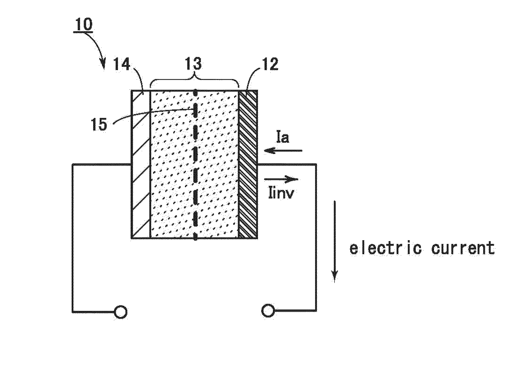
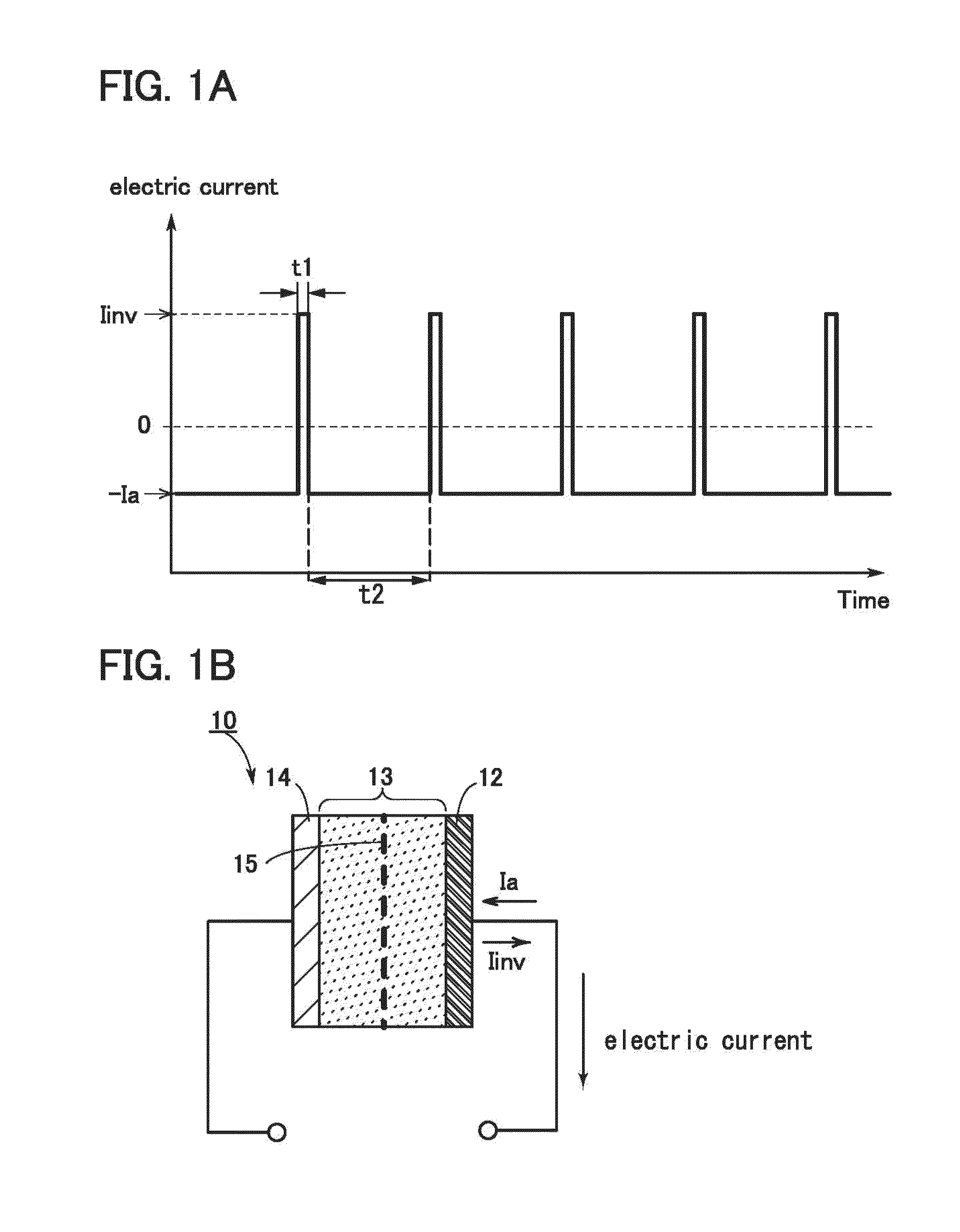
[0115]FIG. 1A shows an example where the absolute value of the reverse pulse current Iinv is larger than that of the current Ia, whereas FIG. 6 shows the case where the absolute value of the reverse pulse current Iinv is smaller than that of the current Ia. Since the current Ia is used for charge, the larger the absolute value of the current Ia is, the shorter the time required for full charge is.

[0116]Note that experiments suggest that the effect of one embodiment of the present invention cannot be obtained only when supply of charge current is stopped momentarily. To obtain the effect, reverse pulse current, which flows in a direction opposite to a direction of current causing lithium deposition, is supplied momentarily (i.e., for a period ranging from 0.1 seconds to 3 minutes, and from 3 seconds to 30 seconds as a typical example). ...

embodiment 3

[0121]The structures of lithium-ion secondary batteries will be described with reference to FIGS. 7A to 7C and FIGS. 8A and 8B.

[0122]FIG. 7A is an external view of a coin-type (single-layer flat type) lithium-ion secondary battery, part of which illustrates a cross-sectional view of the coin-type lithium-ion secondary battery.

[0123]In a coin-type secondary battery 950, a positive electrode can 951 serving also as a positive electrode terminal and a negative electrode can 952 serving also as a negative electrode terminal are insulated and sealed with a gasket 953 formed of polypropylene or the like. A positive electrode 954 includes a positive electrode current collector 955 and a positive electrode active material layer 956 which is provided to be in contact with the positive electrode current collector 955. A negative electrode 957 includes a negative electrode current collector 958 and a negative electrode active material layer 959 which is provided to be in contact with the negat...


PUM


Abstract

When a hole in a separator is clogged, the cycle characteristics of a battery might be lowered and the internal resistance of a battery might be increased to reduce the output. Thus, a means for suppression of or recovery from degradation due to a clogged separator in a battery such as a lithium-ion secondary battery is provided. When reverse pulse current is supplied multiple times during charge, a separator is prevented from being clogged and a voltage increase (increase in internal resistance) during charge is suppressed, so that charge can be normally performed repeatedly.

Description

BACKGROUND OF THE INVENTION[0001]1. Field of the Invention[0002]The present invention relates to an object, a method, or a manufacturing method. In addition, the present invention relates to a process, a machine, manufacture, or a composition of matter. In particular, the present invention relates to, for example, a power storage device, a secondary battery, a driving method thereof, or a fabrication method thereof. In particular, the present invention relates to, for example, an electrochemical device and a driving method of an electrochemical device. In addition, the present invention relates to, for example, a system having a function of reducing the degree of degradation of an electrochemical device.[0003]Note that an electrochemical device in this specification generally means a device that utilizes an electrochemical phenomenon, specifically, a battery or the like.[0004]2. Description of the Related Art[0005]A lithium-ion secondary battery, which is one of electrochemical devi...

Claims


Application Information

Patent Timeline
Patent Type & Authority Applications(United States)
IPC IPC(8): H02J7/00H02J7/02
CPCH02J7/0057H02J7/0069H02J7/00711
Inventor YAMAZAKI, SHUNPEIOGUNI, TEPPEI
Owner SEMICON ENERGY LAB CO LTD
Why Eureka
Try Eureka