Wireless waterline pressure sensor system for self-propelled irrigation systems

a self-propelled irrigation and sensor system technology, applied in the field of self-propelled irrigation systems, can solve the problems of limited monitoring of pressure at such alternative sites, inconvenient installation, and insufficient location of line-of-site telemetry of short-range radios, and achieve the effects of convenient inclusion of short-range radios, adequate power, and scarce and expensive labor

Inactive Publication Date: 2014-08-14
HAALAND KARLYLE
View PDF7 Cites 20 Cited by
  • Summary
  • Abstract
  • Description
  • Claims
  • Application Information

AI Technical Summary

Benefits of technology

[0027]The waterline pressure sensing device is self-contained. The low-power design of the device facilitates inclusion of a short-range radio powered by a lithium-ion battery with or without a solar panel for recharge, both of which are incorporated into the device housing. With the waterline pressure sensing device mounted at the lowest point of a hose-drop serving the outermost sprinkler nozzle, the device will be under the shadow of the crop canopy for much of the growing season. However, the battery is designed to provide adequate power to the waterline pressure sensing device without regular solar recharge. Once the crop is harvested the solar array will recharge the battery as necessary for each successive growing season or the battery can simply be replaced at the beginning of the irrigation season.
[0028]With scarce and expensive labor and high vehicle operating costs, the waterline pressure sensing device when paired with a monitoring MCU offers the operators of mechanized irrigation systems an improved, low cost method of: (a) remotely monitoring the waterline pressure of center pivots to determine if they are running with optimum designed waterline pressure; and (b) using a central server with internet connectivity and wireless telemetry to provide a method of alerting operators to waterline pressure status changes in a timely manner.

Problems solved by technology

The limitation to monitoring pressure at such alternative sites would be the line-of-site telemetry of the short-range radios used.
A suitable location to sense waterline pressure, but not the optimal location since the remaining overhang pipe, that extends up to eighty feet beyond the last drive tower structure, would not be covered for waterline pressure monitoring.

Method used


Image

  • Wireless waterline pressure sensor system for self-propelled irrigation systems
  • Wireless waterline pressure sensor system for self-propelled irrigation systems
  • Wireless waterline pressure sensor system for self-propelled irrigation systems

Examples


Embodiment Construction

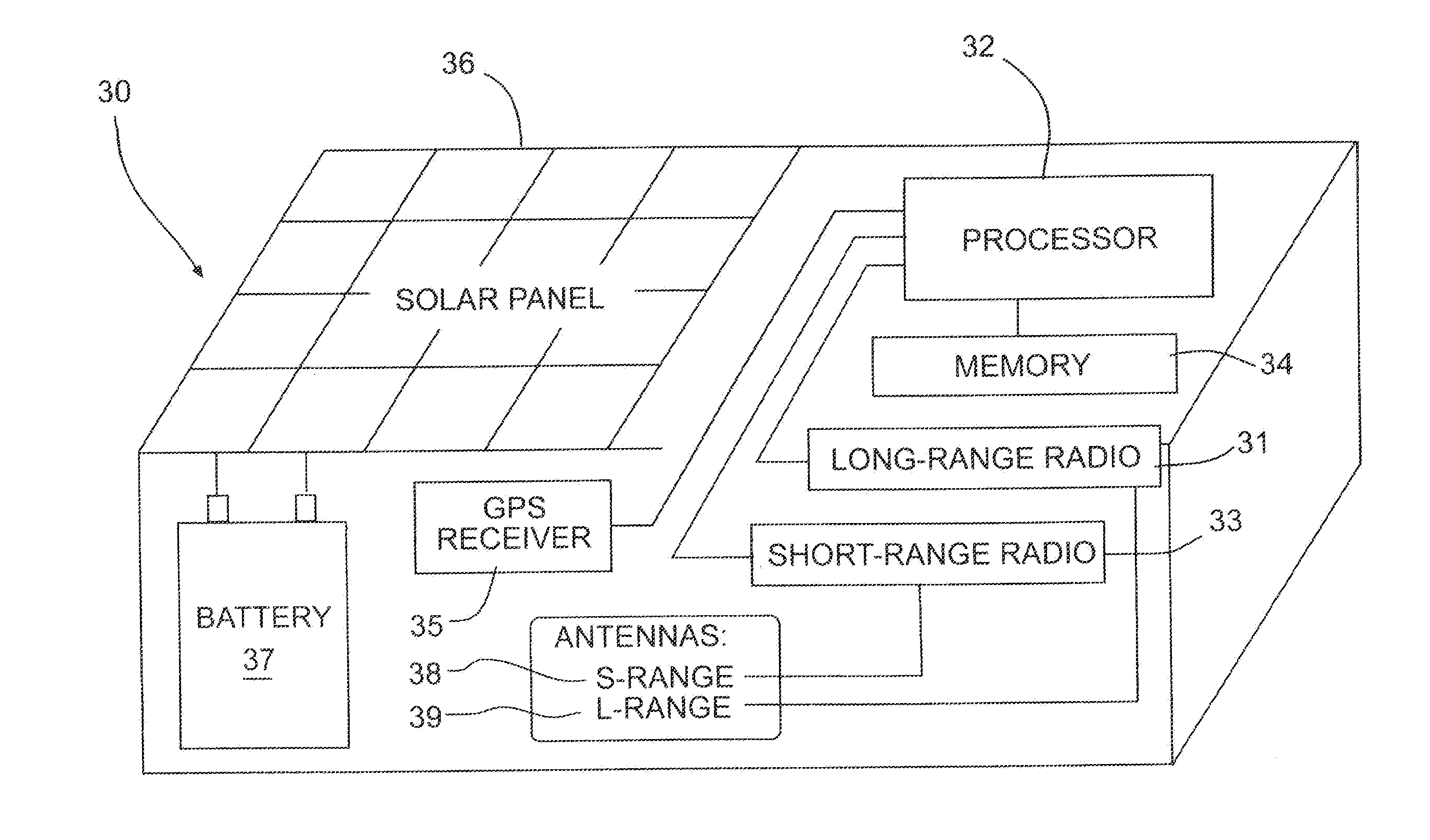
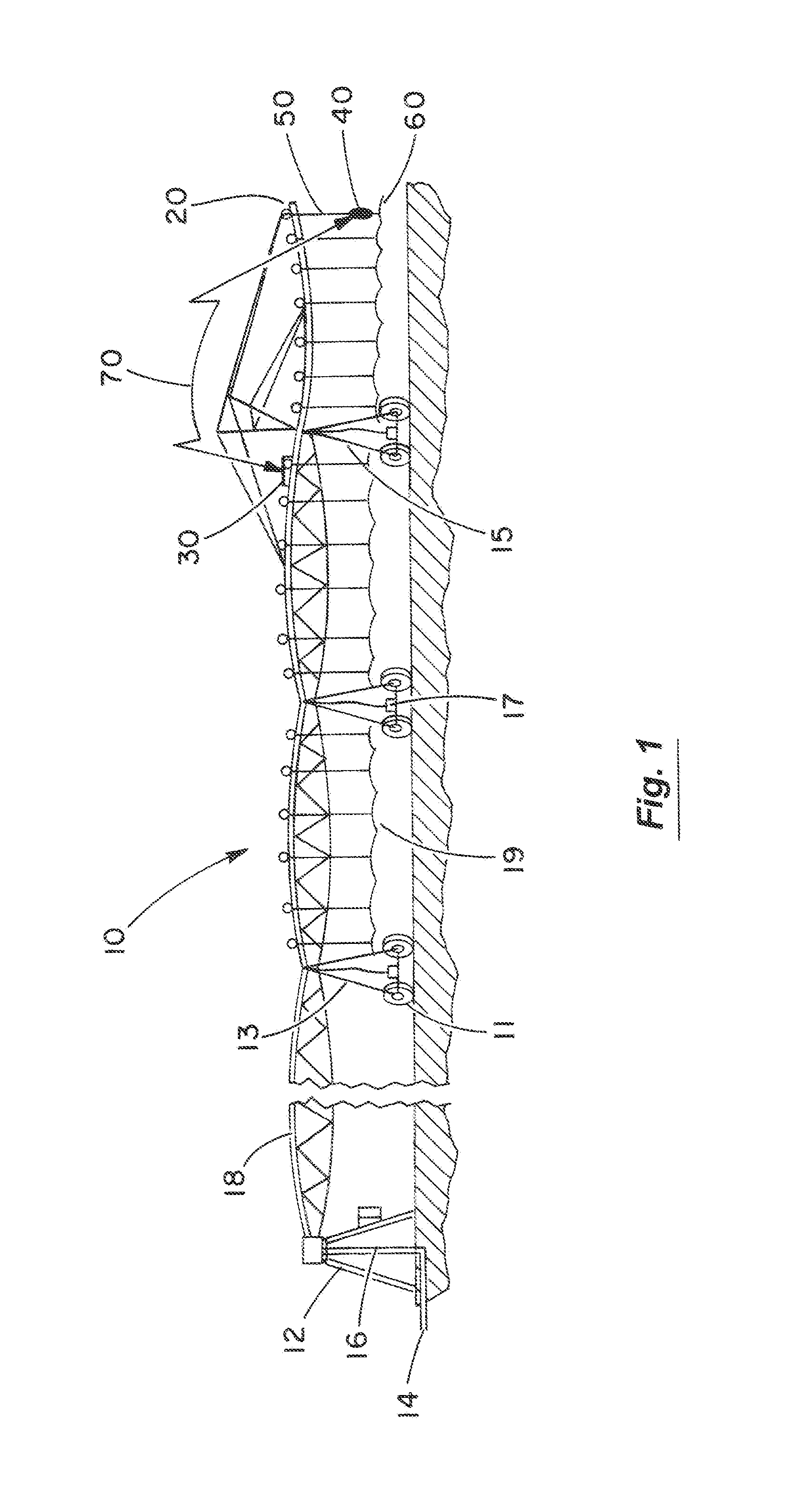
[0042]FIG. 1 is an overview pictorial diagram showing a center pivot irrigation system having a master control unit 30 (MCU) positioned on an outer-most drive tower 15 of a pivot span 18 and having a waterline pressure sensing device 40 located on an outer-most sprinkler nozzle 60 for the purpose of monitoring waterline pressure 16 and using a wireless radio path 70 to communicate between the waterline pressure sensing device 40 and the MCU 30. The invention includes an MCU 30 equipped with a short-range radio 33 (shown in FIG. 3) that communicates locally to a short-range radio 43 (shown in FIG. 4) that is housed in the enclosure of the wireless pressure sensing device 40. Xbee brand radios (commercially available from Digi International of Minnetonka, Minn.) or equivalents are suitable for this purpose. The MCU 30 also includes long-range radio 31 (shown in FIG. 3) for two-way communication with terrestrial or satellite networks.

[0043]FIG. 1 details the mechanized irrigation syste...


PUM


Abstract

A water pressure sensing system for self-propelled irrigation systems has a waterline pressure sensing device mounted at the outermost sprinkler in wireless communications with a master control unit (MCU) mounted elsewhere on the irrigation system. The waterline pressure sensing device includes a water pressure sensor and a processor to detect changes in waterline pressure, in addition to a short-range radio for wireless communication with the MCU. The MCU includes a short-range radio for wireless communication with the water pressure sensing device, a processor for processing the received waterline pressure status data, and a long-range transmitter for relaying this data to a remote internet-connected central computer. The remote central computer alerts mobile operator devices to inform the operator of the waterline pressure status.

Description

BACKGROUND OF THE INVENTION[0001]1. Field of the Invention[0002]The present invention relates generally to the field of self-propelled irrigation systems. More specifically, the present invention discloses a wireless system for remotely monitoring the water pressure at the outermost point of a self-propelled irrigation system.[0003]2. Statement of the Problem[0004]Mechanized sprinkler irrigation systems, such as center pivot and lateral move irrigation systems, are in common use. Over 250,000 exist in the United States alone. Typical systems irrigate over 100 acres to as high as 600 acres. In practice, each center pivot system is designed to deliver a certain flow rate of water (typically expressed in gallons per minute per acre) at a specific waterline pressure uniformly and precisely over the entire field served by the irrigation system. A minimum amount of end-of-system waterline pressure (or at least the presence of water in the outermost point in the waterline) is a defining va...

Claims


Application Information

Patent Timeline
Patent Type & Authority Applications(United States)
IPC IPC(8): G08C17/02
CPCG08C17/02H04Q9/00A01G25/092
Inventor ABTS, GERALD L.
Owner HAALAND KARLYLE
Why Eureka
Try Eureka