Foil bearing

a technology of oil bearings and bearings, which is applied in the direction of sliding contact bearings, mechanical equipment, rotary machine parts, etc., can solve the problems of high temperature exposure of turbine blades mounted to the main shaft, the difficulty of lubricating with liquid lubricating oil, and the difficulty of bearings supporting those main shafts. , to achieve the effect of high accuracy and higher speed

Inactive Publication Date: 2014-08-14
NTN CORP
View PDF2 Cites 14 Cited by
  • Summary
  • Abstract
  • Description
  • Claims
  • Application Information

AI Technical Summary

Benefits of technology

[0028]According to the present invention, a pressure gradient in the axial direction can be generated in the radial bearing gap. Thus, the shaft is rotatable with high accuracy, with the result that the foil bearing that is adaptable to higher speed rotation can be provided.

Problems solved by technology

Further, turbine blades mounted to the main shafts are exposed to high temperature.
Thus, bearings for supporting those main shafts are required to endure severe environments involving high temperature and high speed rotation.
However, use of those bearings is restricted under such conditions that lubrication with a liquid such as a lubricating oil is difficult, that an auxiliary device of a lubricating oil circulatory system is difficult to provide separately in view of energy efficiency, and that shearing resistance of the liquid causes problems.
However, in the air dynamic pressure bearing of this type, when stability limit is exceeded under a state in which management of radial bearing gaps that are formed between the bearing surfaces on the rotary side and the fixed side is insufficient, self-excited centrifugal whirling of a main shaft, which is called a whirl, is liable to occur.
In particular, in environments involving drastic temperature changes as in the case of the gas turbine and the turbocharger, widths of the radial bearing gaps fluctuate due to thermal expansion, and hence the gaps are significantly difficult to manage with high accuracy.
Thus, in consideration of not only a manufacturing tolerance but also the thermal expansion in the drastic temperature changes, the gaps are difficult to strictly manage.

Method used


Image

  • Foil bearing
  • Foil bearing
  • Foil bearing

Examples


Embodiment Construction

[0069]Now, description is made of embodiments of the present invention with reference to the drawings.

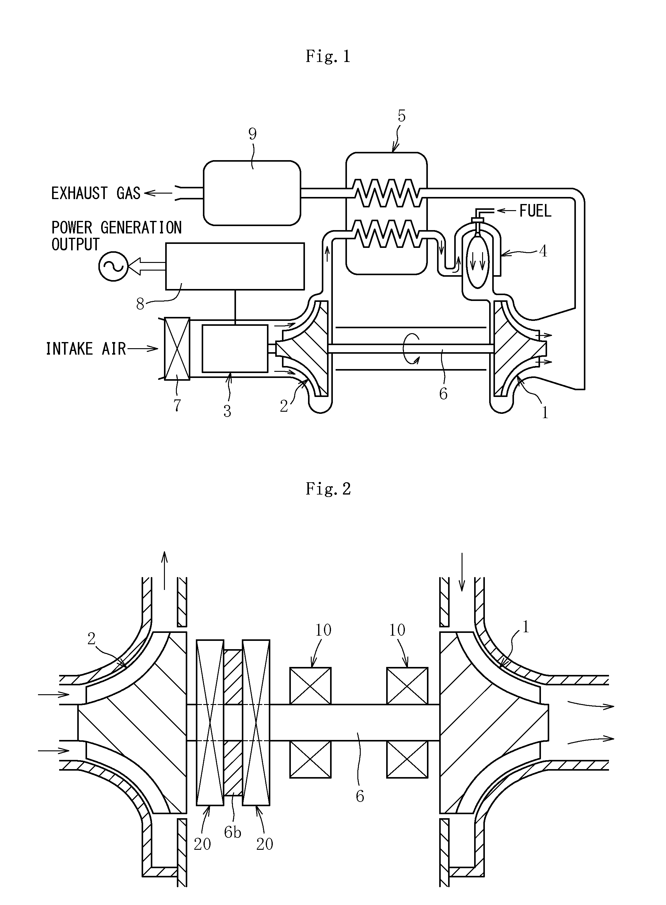
[0070]FIG. 1 is a schematic view of a configuration of a gas turbine apparatus called a micro gas turbine as an example of a turbo-machine. The micro gas turbine mainly comprises a turbine 1 comprising a blade cascade, a compressor 2, a power generator 3, a combustor 4, and a regenerator 5. The turbine 1, the compressor 2, and the power generator 3 comprise a common shaft 6 extending in a horizontal direction. The shaft 6, the turbine 1, and the compressor 2 serve as an integrally rotatable rotor. Air sucked from an air-intake port 7 is compressed by the compressor 2, heated by the regenerator 5, and then fed into the combustor 4. The compressed air is mixed with fuel and combusted so as to rotate the turbine 1 with a high-temperature and high-pressure gas. A rotational force of the turbine 1 is transmitted to the power generator 3 through intermediation of the shaft 6 so as to rota...


PUM

PropertyMeasurementUnit
thicknessaaaaaaaaaa
shapeaaaaaaaaaa
frictional coefficientsaaaaaaaaaa

Abstract

In order have a leaf type foil bearing that is rotatable with high accuracy and adaptable to higher speed rotation, a foil bearing includes a cylindrical outer member, a shaft inserted on an inner periphery of the outer member, and leaves arranged at a plurality of positions in a circumferential direction between an inner peripheral surface of the outer member and an outer peripheral surface of the shaft. A region including a front end of each of the leaves serves as a top foil that has a bearing surface, and a region including a rear end of each of the leaves serves as a back foil that supports, from behind, the top foil of the adjacent leaf. Any one or both of the front end and the rear end of each of the leaves are inclined with respect to an axial direction.

Description

TECHNICAL FIELD[0001]The present invention relates to a foil bearing comprising a thin film foil member interposed between an inner peripheral surface of an outer member and an outer peripheral surface of a shaft.BACKGROUND ART[0002]Main shafts of turbo-machines (for example, a gas turbine and a turbocharger) are driven to rotate at high speed. Further, turbine blades mounted to the main shafts are exposed to high temperature. Thus, bearings for supporting those main shafts are required to endure severe environments involving high temperature and high speed rotation. As bearings for such use, an oil-lubricated rolling bearing or a hydraulic dynamic pressure bearing may be used. However, use of those bearings is restricted under such conditions that lubrication with a liquid such as a lubricating oil is difficult, that an auxiliary device of a lubricating oil circulatory system is difficult to provide separately in view of energy efficiency, and that shearing resistance of the liquid...

Claims


Application Information

Patent Timeline
Patent Type & Authority Applications(United States)
IPC IPC(8): F16C27/02
CPCF16C27/02F16C17/024F16C2360/23F16C2240/60F16C2204/10F16C2223/42F16C2204/72F16C2223/60F16C2206/04F16C33/043F16C2360/24F16C2206/40
Inventor YOSHINO, MASATOFUJIWARA, HIROKI
Owner NTN CORP
Why Eureka
Try Eureka