Unit brake

a unit brake and brake mechanism technology, applied in the direction of brake arrangement with braking member, braking system, braking components, etc., can solve the problems of adverse effects and cannot be exchanged, and achieve the effect of maintaining the bearing performance of the clutch mechanism and preventing unintentional relaxation of the brake for

Active Publication Date: 2014-08-21
NABLESCO CORP
View PDF11 Cites 12 Cited by
  • Summary
  • Abstract
  • Description
  • Claims
  • Application Information

AI Technical Summary

Benefits of technology

[0009]In a unit brake equipped with a cylinder device with a clutch mechanism installed for switching between transmission and blocking the added force of the spring brake part, this Invention takes the above-mentioned situation into consideration to set an objective to provide a unit brake that can prevent unintentional relaxation of the brake force by the spring brake part due to disengagement of the clutch mechanism gripping part, that is a size enabling replacement of existing items, and that can maintain the clutch mechanism bearing performance even during long-term use.
[0012]According to the above-mentioned configuration, the clutch opposing the nut member in the area around the spindle that was positioned in a region in communication with the atmosphere is positioned in the anti-brake direction versus the nut member, and when the clutch mechanism is moved in a linked state, the clutch moves together with the second piston to grip the clutch part of the nut member. In addition, the nut member screwed into the spindle and rotatably supported is supported to enable moving in the anti-brake direction. For this reason, if the compressed fluid in the first pressure chamber of the regular brake part is slowly outgassed, the first piston added force is weakened due to action of the first pressure chamber, and the first piston is pushed in the anti-brake direction by the spring-back reaction force from the brake shoe side, the nut member will be pushed in deeply gripping direction toward the clutch. With this action, even if the compressed fluid in the first pressure chamber is outgassed and the spring-back reaction force from the brake shoe side is activated, the disengagement of the gripping part with the nut member and clutch in the clutch mechanism is prevented. As a result, unintentional relaxation of the brake force in the spring brake part that is used as a parking brake, etc., is prevented.
[0013]In addition, with the above-mentioned configuration, the loosening of the mutual gripping part in the clutch mechanism, and the unintentional relaxation of braking force due to the spring brake part can be prevented. Furthermore, since a protruding part as seen in Patent Citation 2 is not generated in the cylinder back part, the installation space problem can also be solved.
[0014]In addition, with the above-mentioned configuration, since the first pressure chamber in the anti-brake direction of the clutch box holding the bearing is installed, exposure of the bearing to the compressed fluid can be prevented. In addition, in the same way, since the second pressure chamber on the outer side of the clutch box holding the bearing on the inner side is installed, exposure of the bearing to the compressed fluid can be prevented. Furthermore, since air surrounding the bearing flows smoothly, even if the atmosphere becomes humid, if the atmosphere afterward becomes drier, the atmosphere around the bearing also dries out. As a result, since grease applied to the bearing can be prevented from deterioration due to oil or water incorporated in the compressed fluid, it can maintain performance even through long-term use.
[0016]With the above-mentioned configuration, the air in the atmosphere passes through a specified gap formed between the spindle and clutch, and transits between the clutch and nut member to adequately supply the region where the clutch disengagement spring is positioned. It follows that, even if the atmosphere becomes humid, if the atmosphere afterward becomes drier, the air in the region where the clutch disengagement spring is positioned also dries out. As a result, grease applied to the bearing can more surely prevent deterioration due to a humid atmosphere.

Problems solved by technology

As a result, there are cases where the convex-concave teeth in the nut member and sleeve member do not fully grip all the way to the back, and the rod and second piston remain linked with only the forward tip parts gripped together.
In addition, while use of the unit brake listed in Patent Citation 2 (Laid Open No. 2010-164193 Publication) solves the above-mentioned issue, there is a problem in that it cannot be exchanged as is for existing vehicles where the Patent Citation 1 (Laid Open No. 2008-101766 Publication) unit brake is used, because of an installation space problem.
Furthermore, since the bearing used in the clutch mechanism of the unit brake listed in Patent Citation 2 (Laid Open No. 2010-164193 Publication) is used inside a compressed air atmosphere generated by a compressor, there is a problem of adverse effects due to humidity, etc.
In particular, the said problem appears quite notably in cases of vehicles used overseas where dehumidification devices are not installed.

Method used


Image

  • Unit brake
  • Unit brake
  • Unit brake

Examples


Embodiment Construction

[0043]Here follows a description of the unit brake related to the Embodiment of this Invention, with reference to the illustrations.

[0044]100>

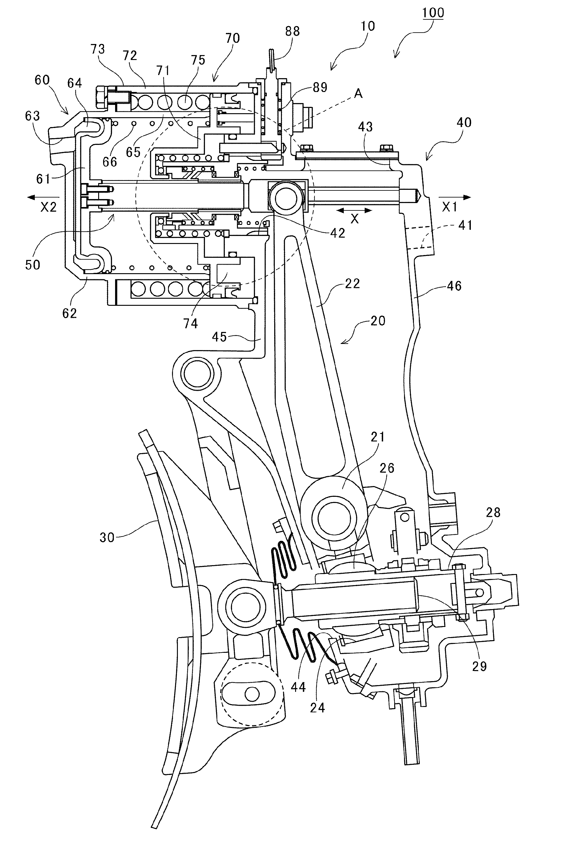
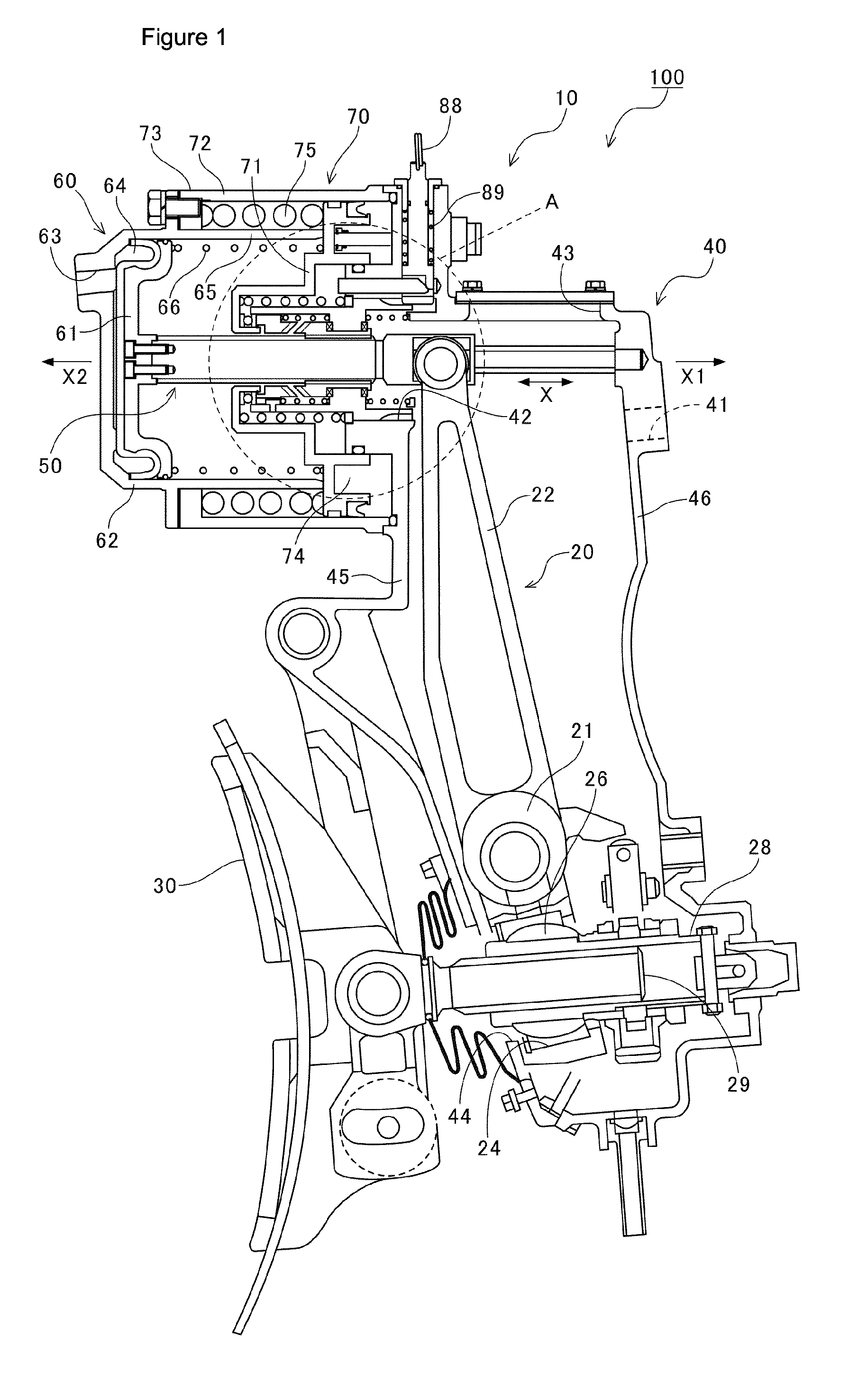
[0045]The unit brake 100 related to the Embodiment of this Invention is configured as a railroad car brake device. This unit brake 100 is equipped mainly with a cylinder device 10 for generating force, a brake lever 20 enabling swivel motion versus the movement of the cylinder device 10, a brake shoe receptacle 30 that can be moved forward and back by the swivel motion of the brake lever 20, and on which is mounted a brake shoe not shown in the illustration, a casing 40 that is formed in a hollow shape, and with an interior that enables communication with the atmosphere. In this casing 40, a connection hole 41 is formed, and a bolt not shown in the illustration inserted into this connection hole 41 is set so that the casing 40 can be fixed to a vehicle carriage.

[0046]20>

[0047]The brake lever 20 is housed in the casing 40. This brake lever 20 i...


PUM


Abstract

Disclosed is unit brake, which is equipped with a cylinder apparatus in which a clutch mechanism that switches between transmitting or cutting off a biasing force of a spring brake part is disposed, is capable of preventing a braking force due to the spring brake part from unintentionally decreasing due to a meshing section of the clutch mechanism disengaging, and is of a size that can replace an existing unit brake, and maintains the performance of bearings in the clutch mechanism even with long-term use. The clutch mechanism of the unit brake includes: a nut member that rotatably screws on a spindle that is positioned in an area that communicates with the atmosphere, and is movably supported in a direction opposite to braking; a clutch that is disposed in a direction opposite to braking with respect to the nut member, and faces the nut member in the vicinity of the spindle; a clutch box that is formed in a cylinder shape, and houses the nut member and clutch on the inside; and bearings that rotatably support the nut member on the inside of the clutch box.

Description

TECHNOLOGY FIELD[0001]This Invention relates to a unit brake with a regular brake part and a spring brake part.BACKGROUND TECHNOLOGY[0002]A cylinder device and a brake body attached to this cylinder device are equipped as a unit brake for vehicle braking, to activate the cylinder device, and bring a brake shoe retaining relative displaceability versus the brake body into contact with the vehicle wheel, to brake the rotation of the vehicle wheel. For the cylinder device in this type of unit brake, for example, in brake devices for rail vehicles, cylinder devices are known that can be activated with both a regular brake part activated with compressed air (compressed fluid) used in normal operations, and a spring brake part activated by a spring force even without use of compressed air, used for stopping the vehicle over a long time (see Patent Citation 1). In the cylinder device disclosed in Patent Citation 1, the regular brake part has a rod protruding and has installed a first pisto...

Claims


Application Information

Patent Timeline
Patent Type & Authority Applications(United States)
IPC IPC(8): F16D65/28B61H1/00B61H13/00F16D49/00
CPCF16D65/28F16D49/00B61H13/005B61H13/00B61H1/00B60T1/04B60T17/086F16D2121/04F16D2121/06F16D2123/00F16D2127/04
Inventor ASANO, YOSHIO
Owner NABLESCO CORP
Why Eureka
Try Eureka