Hydraulic control device

a control device and hydraulic technology, applied in the direction of rotary clutches, fluid couplings, gearings, etc., can solve the problems of increasing the number of components, achieve the effects of stabilizing the pressure difference, improving the controllability of the lock-up clutch, and reducing the hydraulic pressur

Active Publication Date: 2014-08-21
AISIN AW CO LTD
View PDF3 Cites 2 Cited by
  • Summary
  • Abstract
  • Description
  • Claims
  • Application Information

AI Technical Summary

Benefits of technology

[0025]The hydraulic control device according to the present invention includes the switcher which switches between the first state in which connection between the engagement oil passage communicated with the engagement oil chamber and the first output oil passage connected to the output port of the pressure regulation valve is allowed and connection between the circulation input oil passage communicated with the circulation oil chamber and the second output oil passage connected to the output port of the pressure regulation valve is allowed, and the second state in which connection between the engagement oil passage and the first output oil passage is blocked and connection between the circulation input oil passage and the second output oil passage is blocked, and the orifice is formed in the second output oil passage. This allows the output of the pressure regulation valve to be supplied to the engagement oil passage directly, and allows the output of the pressure regulation valve to be supplied to the circulation input oil passage via the orifice, which makes it possible to engage the lock-up clutch by controlling a pressure difference between the hydraulic pressure in the engagement oil chamber and the hydraulic pressure in the circulation oil chamber using the same output from the pressure regulation valve. As a result, it is possible to stabilize the pressure difference, which improves the controllability of the lock-up clutch. In addition, the circulation output oil passage is connected to the circulation output port side of the circulation oil chamber, and the output port of the pressure regulation valve is connected to the circulation input port side of the circulation oil chamber via the circulation input oil passage, the switcher, the second output oil passage, and the orifice. Thus, the hydraulic pressure in the circulation oil chamber can be drained from the circulation output oil passage side, and can be drained from the circulation input oil passage side as well along with pressure regulation performed by the pressure regulation valve. As a result, it is possible to immediately reduce the hydraulic pressure in the circulation oil chamber, which further improves the controllability of the lock-up clutch. In addition, the hydraulic control device includes the pump which generates a hydraulic pressure using power of the motor, the hydraulic pressure generator which generates the line pressure which is high and the secondary pressure which is lower than the line pressure on the basis of the hydraulic pressure generated by the pump, the line pressure oil passage supplied with the line pressure, and the secondary pressure oil passage supplied with the secondary pressure, the input port of the pressure regulation valve is connected to the line pressure oil passage, and the switcher further blocks connection between the secondary pressure oil passage and the circulation input oil passage in the first state, and further allows connection between the secondary pressure oil passage and the circulation input oil passage in the second state. This allows the line pressure which is higher to be supplied to the engagement oil chamber, which allows the lock-up clutch to be engaged even if the rotational speed of the motor is relatively low. In addition, the secondary pressure can be supplied to the circulation oil chamber as the circulation pressure when the lock-up clutch is to be disengaged, which prevents a reduction in line pressure. Here, the term “orifice” means pressure reducing means for reducing a hydraulic pressure within the second output oil passage (pressure suppressing means for suppressing the pressure of hydraulic oil within the second output oil passage).
[0026]The hydraulic control device according to the present invention may further include: a bypass oil passage connected to the first output oil passage so as to bypass the orifice; and a one-way valve that is attached to the bypass oil passage and that opens only in such a direction that the circulation pressure is discharged from the circulation input port. This configuration makes it is possible to improve the performance of drainage of the hydraulic pressure in the circulation oil chamber from the circulation input oil passage side.
[0027]The hydraulic control device according to the present invention may further include a relief oil passage provided with a relief valve that opens when a hydraulic pressure that is equal to or more than a set pressure is applied, and the switcher may further block connection between the engagement oil passage and the relief oil passage in the first state, and further allow connection between the engagement oil passage and the relief oil passage and connection between the circulation output oil passage and the relief oil passage in the second state. This configuration allows the engagement oil chamber to be filled with hydraulic oil also when the lock-up clutch is disengaged, which allows the lock-up clutch to be immediately engaged next time.

Problems solved by technology

In this case, different valves are required to control the respective hydraulic pressures, which increases the number of components.

Method used


Image

  • Hydraulic control device
  • Hydraulic control device
  • Hydraulic control device

Examples


Embodiment Construction

[0033]A best mode of implementing the present invention will be described below with reference to an embodiment.

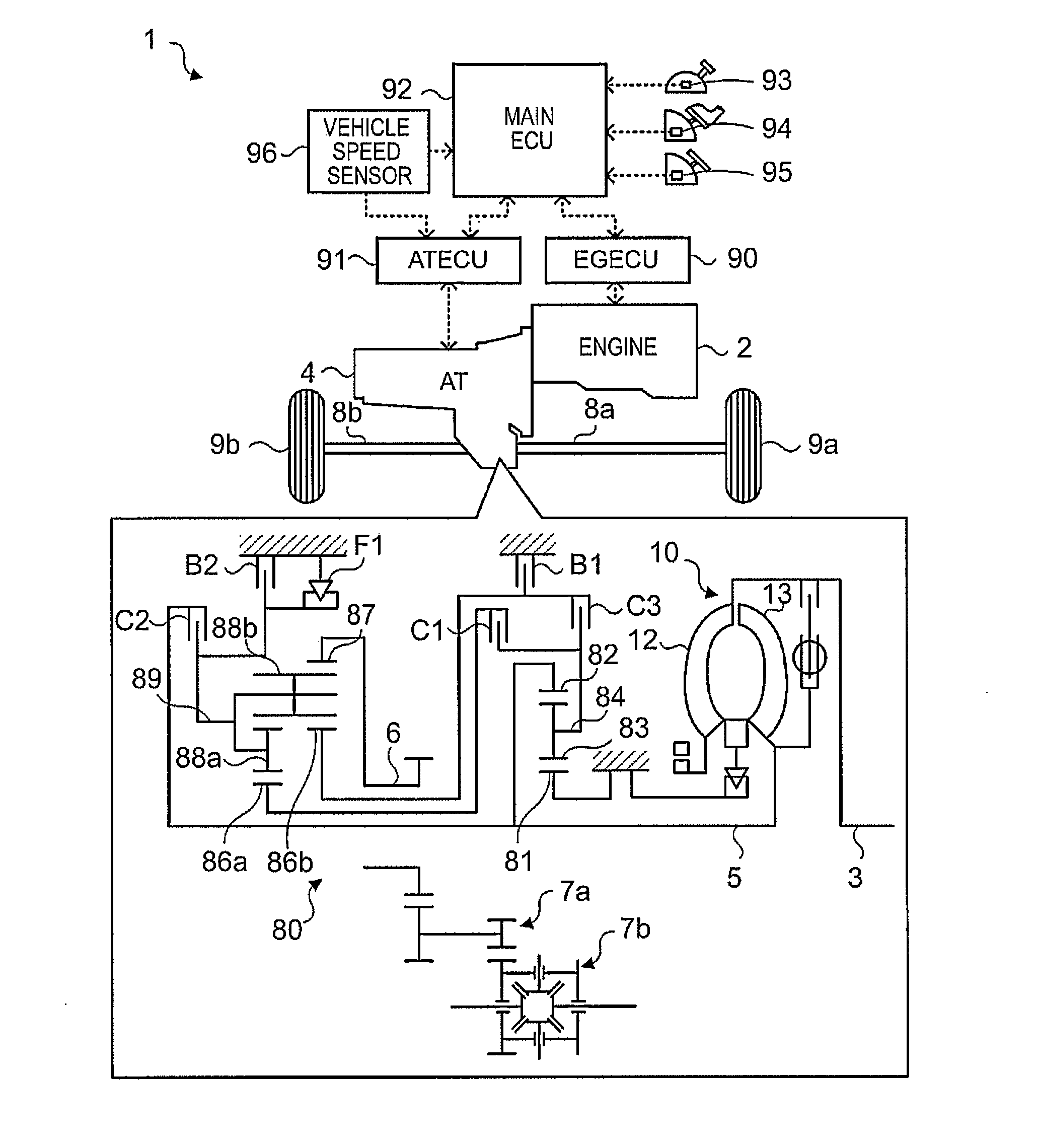
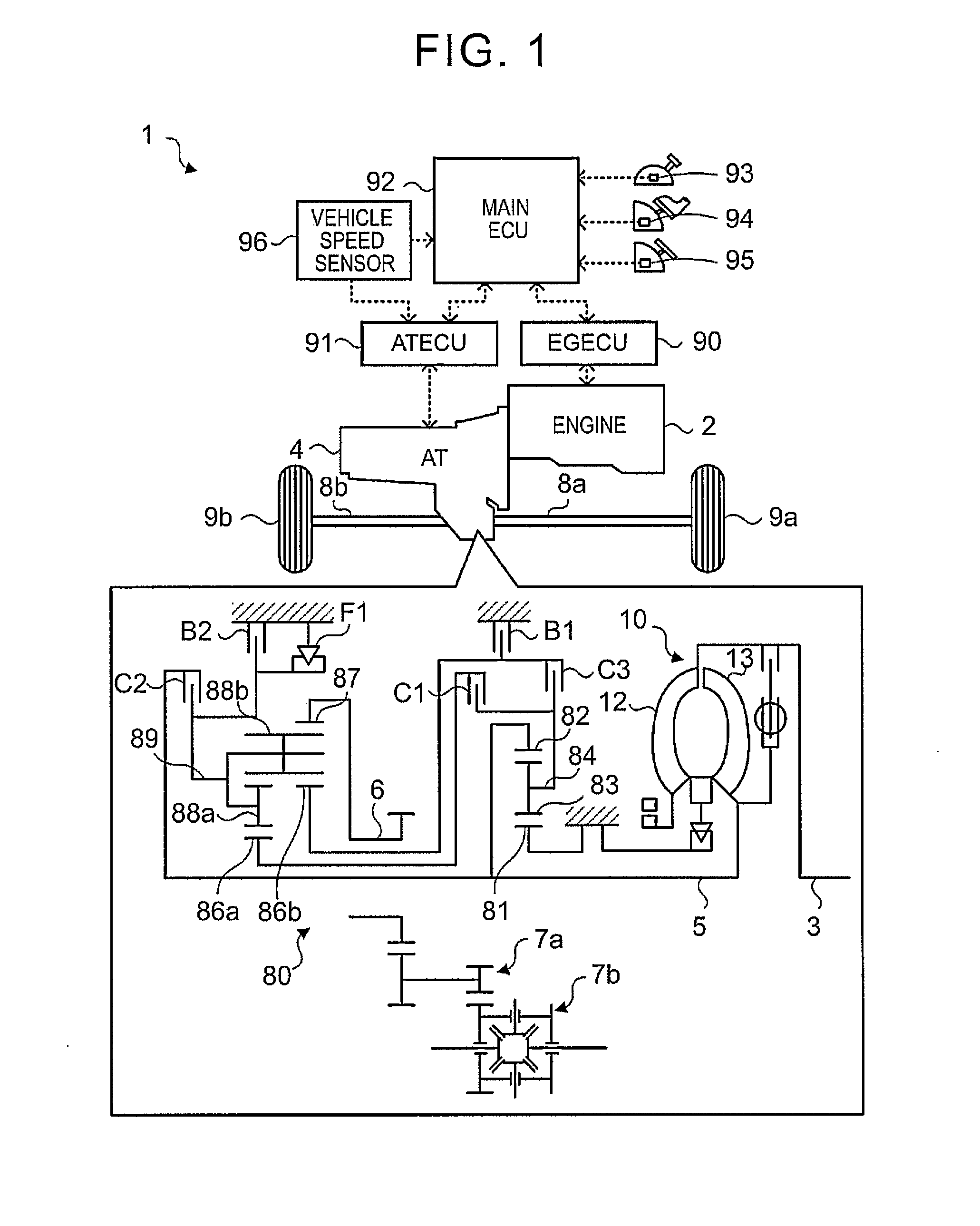
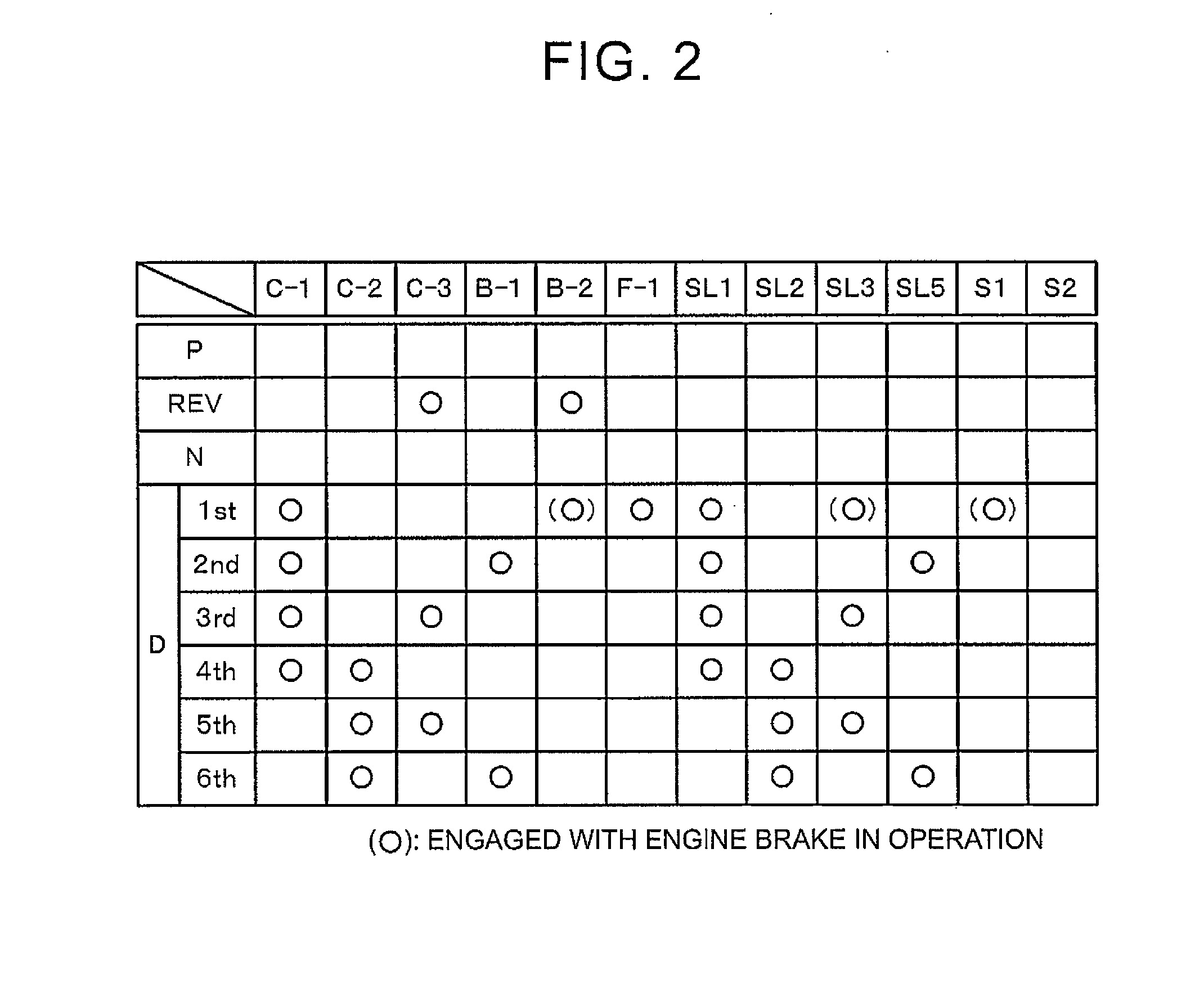
[0034]FIG. 1 is a diagram illustrating a schematic configuration of an automobile 1. FIG. 2 is an operation table of a speed change mechanism 80. FIG. 3 is a diagram illustrating a schematic configuration of a hydraulic control device 30 according to the embodiment of the present invention. FIG. 4 illustrates operation of the hydraulic control device 30 according to the embodiment in disengaging a lock-up clutch 20. FIG. 5 illustrates operation of the hydraulic control device 30 according to the embodiment in engaging the lock-up clutch 20.

[0035]As illustrated in FIG. 1, the automobile 1 includes: an engine 2 which is an internal combustion engine that outputs power generated by explosive combustion of a hydrocarbon fuel such as gasoline and light oil; an engine electronic control unit (engine ECU) 90 that controls operation of the engine 2; an automatic transmission 4 tha...


PUM


Abstract

A hydraulic control device includes a lock-up control valve that regulates a line pressure to generate a control pressure, and a lock-up relay valve that switches between paths through which a hydraulic pressure is supplied to and discharged from a torque converter. The lock-up relay valve is formed to be capable of switching between a path that connects between a control pressure oil passage to which the control pressure is output and a lock-up oil passage communicated with a lock-up oil chamber and that connects between a control pressure oil passage to which the control pressure is output and a circulation input oil passage communicated with a converter oil chamber, and a path that blocks connection between the control pressure oil passage and the lock-up oil passage and that blocks connection between the control pressure oil passage and the circulation input oil passage.

Description

TECHNICAL FIELD[0001]The present invention relates to a hydraulic control device that controls a hydraulic pressure for a torque converter with a lock-up clutch.BACKGROUND ART[0002]Hitherto, there has been proposed a hydraulic control device of this type that controls a hydraulic pressure for a torque converter with a lock-up clutch having a fluid transmission chamber (circulation oil chamber) connected to a torque converter input-side oil passage and a torque converter output-side oil passage, and a lock-up clutch hydraulic pressure chamber (engagement oil chamber) to which a lock-up clutch oil passage is connected (see Patent Document 1, for example). The device includes a lock-up relay valve having a switching portion that switches between a state in which a secondary pressure is supplied to the torque converter input-side oil passage directly and a state in which the secondary pressure is supplied to the torque converter input-side oil passage via an orifice, and a switching por...

Claims


Application Information

Patent Timeline
Patent Type & Authority Applications(United States)
IPC IPC(8): F16H45/02
CPCF16H45/02F16H61/14F16H2061/0425F16H61/0206F16H61/143
Inventor JINNO, TOMOYAISHIKAWA, TOMOMIYAMAGUCHI, MASAMICHISHIMIZU, TETSUYAISHIKAWA, KAZUNORI
Owner AISIN AW CO LTD
Why Eureka
Try Eureka