Digitally scanned multi-cell electro-optic sensor

a multi-cell, electro-optic sensor technology, applied in the field of electro-optic sensors, can solve the problems of system failure, system failure to completely miss the target, and passive imaging mode does not have the sensitivity to acquire and track the target at long ranges at the desired update, etc., to achieve the effect of increasing signal strength, reducing integration period and reducing the number of times

Active Publication Date: 2014-08-21
RAYTHEON CO
View PDF2 Cites 26 Cited by
  • Summary
  • Abstract
  • Description
  • Claims
  • Application Information

AI Technical Summary

Benefits of technology

[0022]In an embodiment, the EO sensor further comprises a processor that provides control signals to the SLM to control the addressable elements to time demultiplex portions of the FOV that are spatially overlapped on the imaging detector and to the imaging detector to read out the electrical signals over an integration period to stitch together one or more images at varying resolution. The processor may control the SLM to concurrently interrogate different areas of the FOV that are mapped to different detector cells to stitch together sub-images with different resolutions. The processor may calculate a signal-to-noise ratio (SNR) of the object in the image(s) to set a minimum integration period to maintain at least a minimum SNR. The minimum integration period bounds the time demultiplexing and the resolution of the image(s). As the distance between the EO sensor and object closes, the signal strength increases and the minimum integration period required to maintain the minimum SNR is reduced allowing for greater time demultiplexing to stitch together higher resolution images.

Problems solved by technology

However, due to its much higher spatial resolution, hence fewer incident photons per pixel, the passive imaging mode does not have the sensitivity to acquire and track the target at long ranges at the desired update rate.
However, in a dynamic scene that requires feedback at a particular update rate these systems are less than ideal.
If a target is moving quickly through a scene, the act of scanning through that scene could cause the system to miss the target entirely.
This approach strikes a balance of cost between the detector and the opto-mechanical platform.
However, unlike the digital camera industry that utilizes Silicon detector technology in the visible band, the push to larger and larger format detector arrays in the SWIR, MWIR and LWIR bands have not been followed by a reduction in cost of the detector for infrared systems.
As users demand more resolution across a wider FOV the detector cost, and cost to cool the detector, have become the most expensive component in the electro-optic sensor system.
However, as the users of current electro-optic sensors have become accustomed to the performance provided by a staring FPA, those users have hesitated to move back to a single pixel architecture that demands significant processor resources, cannot maintain the high update rates and cannot concurrently interrogate different areas of the FOV.
The opto-mechanical scanning and staring FPA single-mode systems must either accept a shorter acquisition range or provide large and expensive optical systems to increase sensitivity.
The Rice pixel cannot instantly interrogate the entire FOV and has limited performance in dynamic scenes.

Method used


Image

  • Digitally scanned multi-cell electro-optic sensor
  • Digitally scanned multi-cell electro-optic sensor
  • Digitally scanned multi-cell electro-optic sensor

Examples


Embodiment Construction

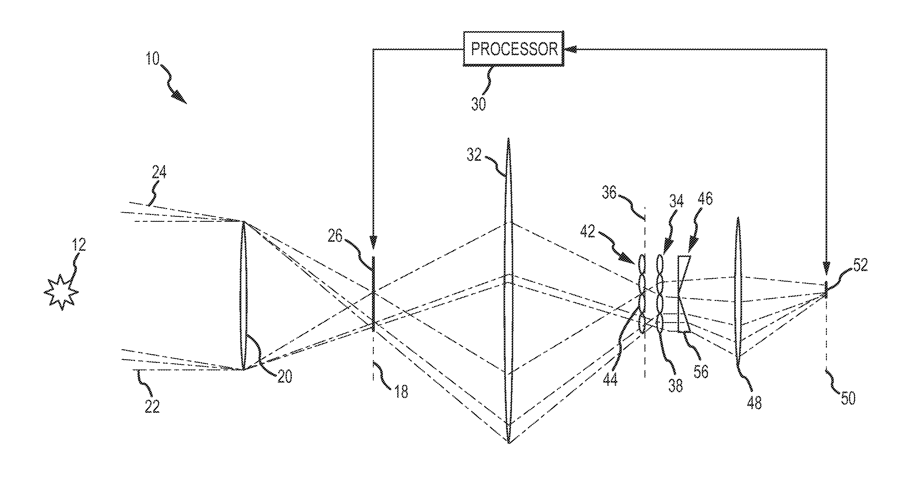
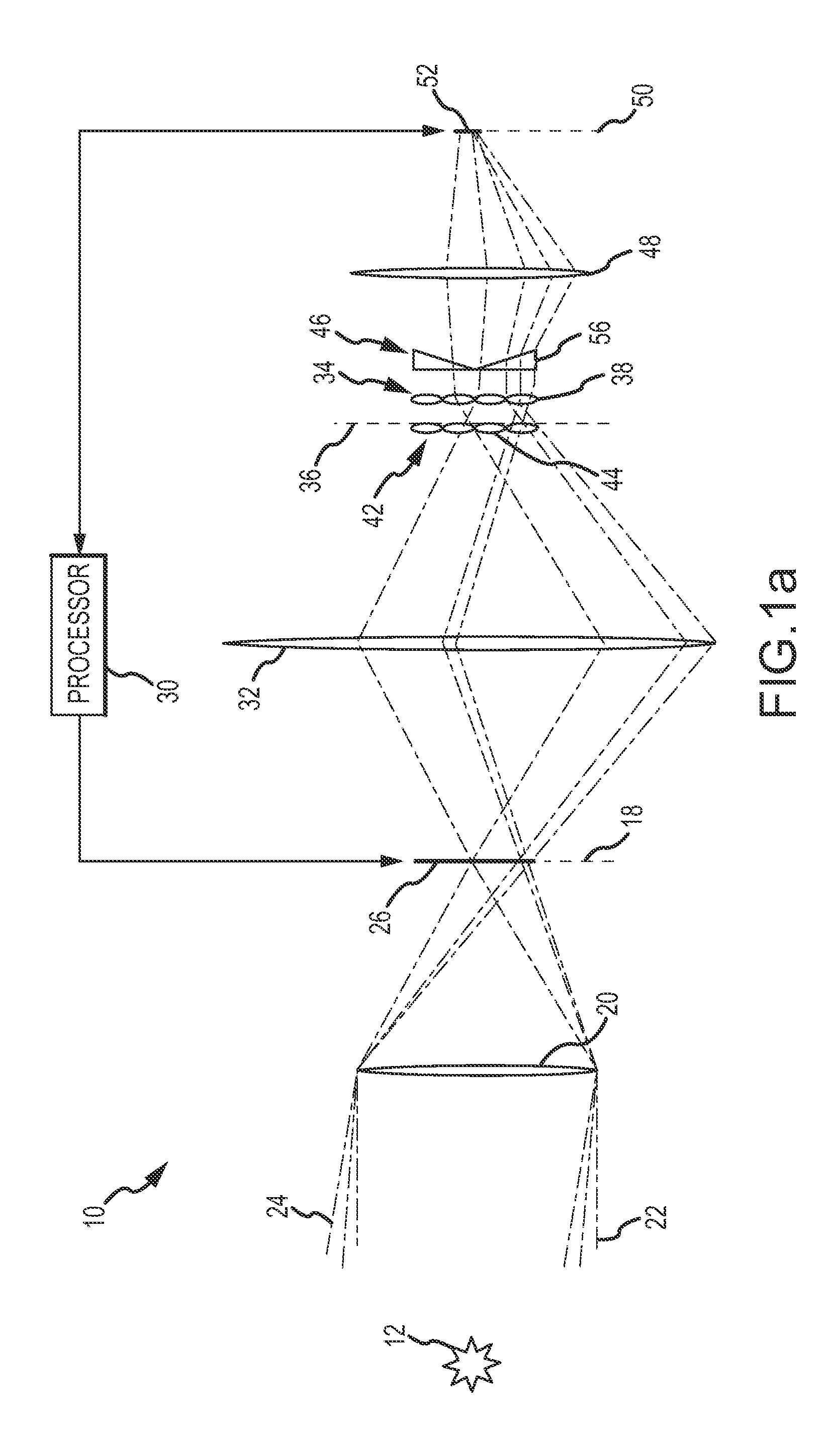
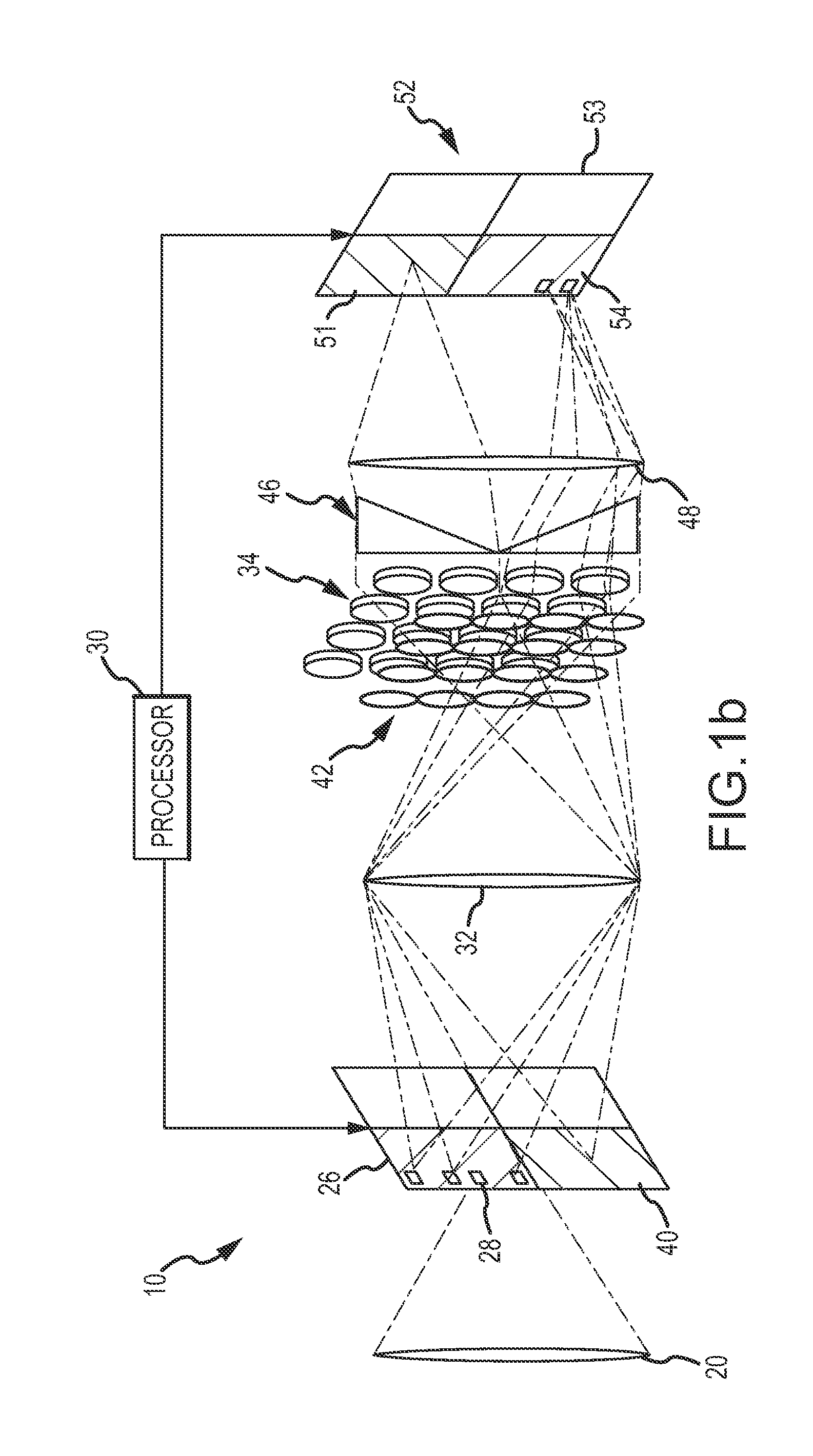
[0030]The present invention provides a digitally scanned multi-cell EO sensor that provides capabilities similar to those of a dual-mode EO sensor with a single low-resolution imaging detector. The digitally scanned multi-cell EO sensor can be used in many applications including but not limited to guided munitions (e.g. self-propelled missiles, rockets, kinetic weapons, gun-launched projectiles or aerial bombs), satellites, space-launched kill vehicles, unmanned aerial vehicles (UAVs) and surveillance systems. Other potential uses include for guidance systems for autonomous cars or aircraft or ships and specific uses such as automated aerial refueling, ship docking or aircraft landing systems. The digitally scanned multi-cell EO sensor can be used in any system in which the EO sensor needs to provide (a) high detection sensitivity at long ranges to the object accepting low image resolution and (b) high resolution at short ranges to the object. The digitally scanned multi-cell EO sen...


PUM


Abstract

A digitally scanned multi-cell EO sensor comprises a low-resolution multi-cell imaging detector. An array of optical focusing elements decomposes the sensor's FOV into at least four sub-fields. A sub-field directing array and focusing optic direct the optical radiation onto the imaging detector. In a first tilt mode, the optical radiation from the sub-fields is directed into at least four spatially separated sub-regions that each map to a different detector cell. A high-resolution spatial light modulator (SLM) digitally scans the FOV to select different portions of the FOV to map onto the different detector cells to time demultiplex spatially overlapping portions of the FOV onto each detector cell to stitch together a sub-image of a selected area of the FOV up to the native resolution of the SLM.

Description

RELATED APPLICATION[0001]This patent application is related to United States patent application entitled “Multi-Plenoptic System With Image Stacking and Method for Wide Field-of-Regard High Resolution Imaging”, Ser. No. 13 / 371,984, filed Feb. 13, 2012, the entire contents of which is incorporated by reference.BACKGROUND OF THE INVENTION[0002]1. Field of the Invention[0003]This invention relates to electro-optic (EO) sensors for image formation, and more particularly to a digitally scanned multi-cell EO sensor that provides capabilities similar to those of a dual-mode EO sensor.[0004]2. Description of the Related Art[0005]Many guided munitions (e.g. self-propelled missiles, rockets, gun-launched projectiles or aerial bombs) use a dual-mode EO sensor to guide the munition to its target. In a semi-active laser (SAL) mode, the sensor detects active guidance radiation in the form of laser radiation from a SAL designator that is reflected off of the target and locks onto the laser spot to...

Claims


Application Information

Patent Timeline
Patent Type & Authority Applications(United States)
IPC IPC(8): H01L27/146
CPCH01L27/14625F41G7/008F41G7/2253F41G7/226F41G7/2293G01S3/781G01S3/784G02B26/0875G02B26/10H04N5/33H04N25/00
Inventor STREUBER, CASEY T.PFLIBSEN, KENT P.EASTON, MICHAEL P.
Owner RAYTHEON CO
Why Eureka
Try Eureka