Dry-wet spinning device and method for manufacturing synthetic fiber
a technology of synthetic fiber and spinning device, which is applied in the direction of manufacturing tools, melt spinning methods, artificial filament chemical after-treatment, etc., can solve the problem of inability to carry out dry-wet spinning, and achieve the effect of effectively suppressing the vibration of a coagulating liquid surface and stable spinning
- Summary
- Abstract
- Description
- Claims
- Application Information
AI Technical Summary
Benefits of technology
Problems solved by technology
Method used
Image

Examples
example 1
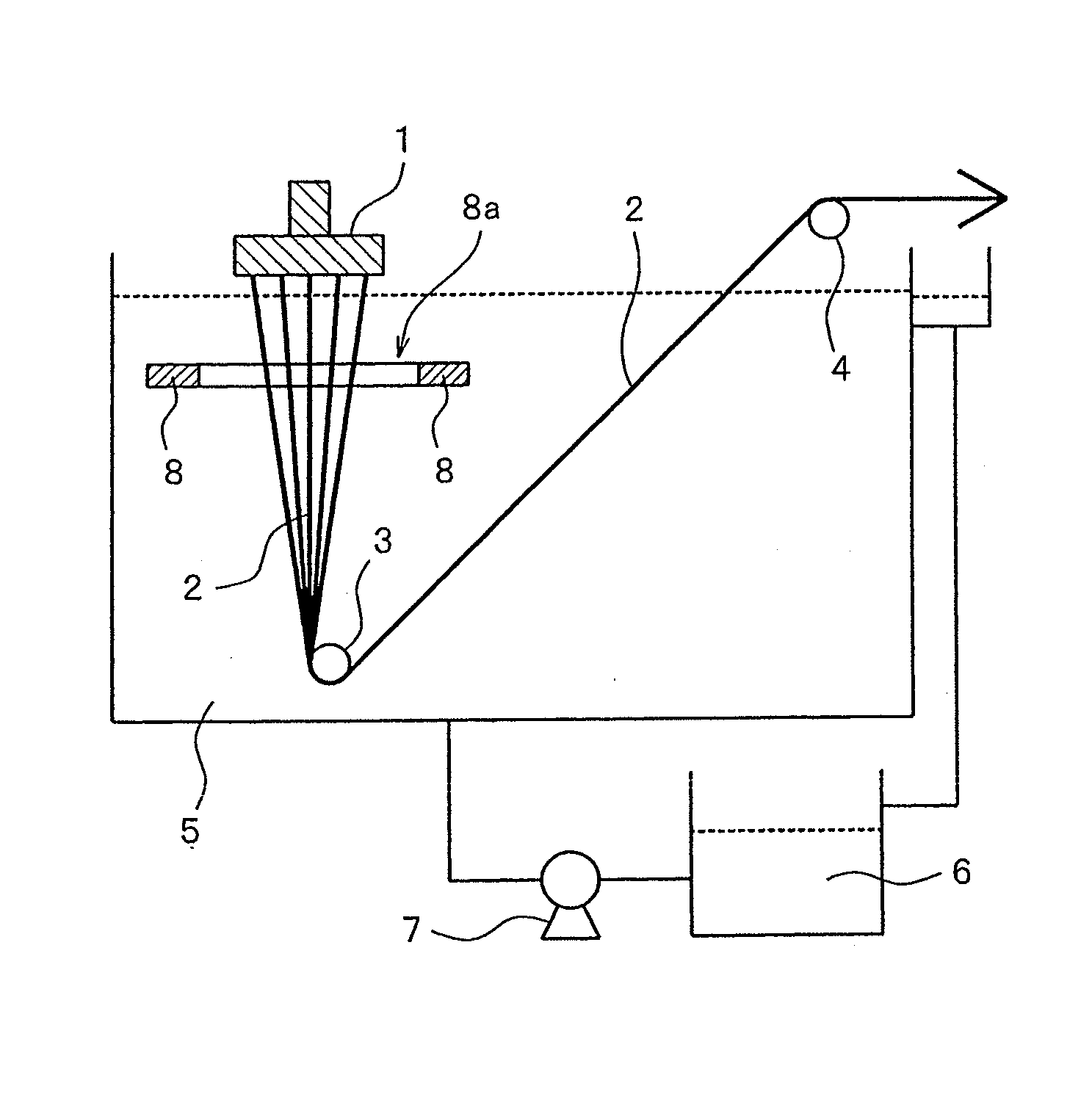
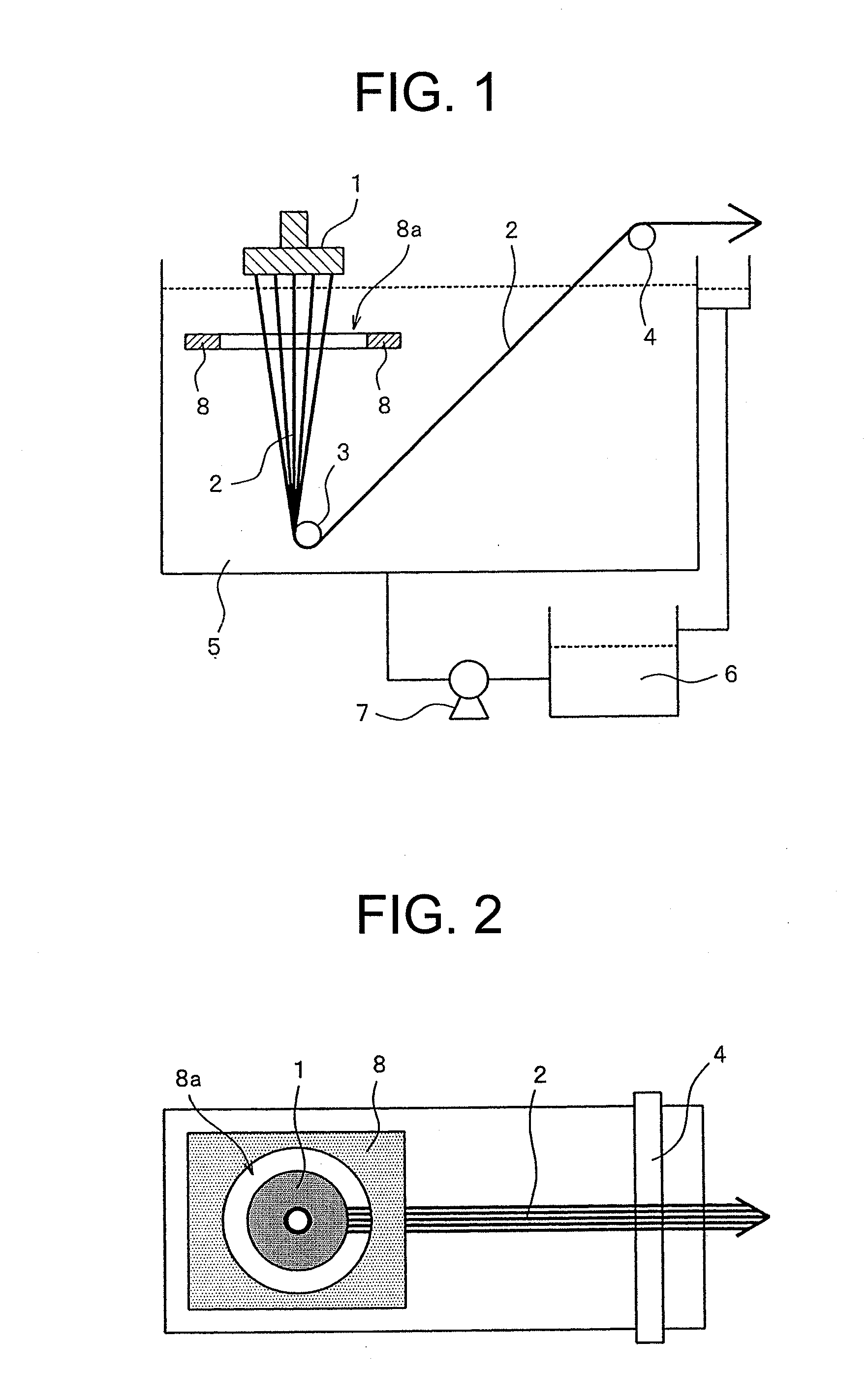
[0094]A polymer consisting of 96% by mass of acrylonitrile, 1% by mass of methacrylic acid, and 3% by mass of methyl acrylate with extreme viscosity [η] of 1.8 was dissolved in dimethyl acetamide to prepare a stock solution for spinning in which the polymer concentration is 23% by mass. The stock solution for spinning was filtered through a 20μ and 5μ filter, kept at 70° C., and then spun according to the dry-wet spinning method by using a spinneret with a diameter of 0.15 mm and 3000 holes and the device illustrated in FIGS. 12 and 13 to obtain a coagulated fiber. The stock solution for spinning was introduced to the coagulation bath while composition of the coagulation bath was dimethyl acetamide / water=78 / 22 (% by mass), a temperature was 15° C., and the distance between the nozzle surface and the coagulation bath was 4 mm.
[0095]The obtained coagulated fiber was drawn in air, subsequently subjected to a drawing washing in hot water, and then treated with a silicone-based oil prepa...
example 2
[0098]As illustrated in FIGS. 14 and 15, a stock solution for spinning was prepared at the same condition as Example 1 and the spinning was performed by following the same operations except that a vertical flow straightening plate extending in a downward reaction from the outer periphery of the horizontal flow straightening plate to the bottom surface of the coagulation bath is not installed. Meanwhile, the material of the vertical flow straightening plate was a wire mesh manufactured by Kansai Wire Netting Co., Ltd. (14 mesh, a line diameter of 0.29 mm, a mesh size of 1.52 mm, and a material: SUS304). The results obtained from the vibration state of the coagulating liquid surface and the observation by an electron microscope of a cross-section of the fiber bundle which has been obtained as a drawn fiber, and the evaluation of the presence or absence of staple fiber adhesion based on dispersion test are listed in Table 1.
[0099]Further, the maximum flow rate on the liquid surface in ...
example 3
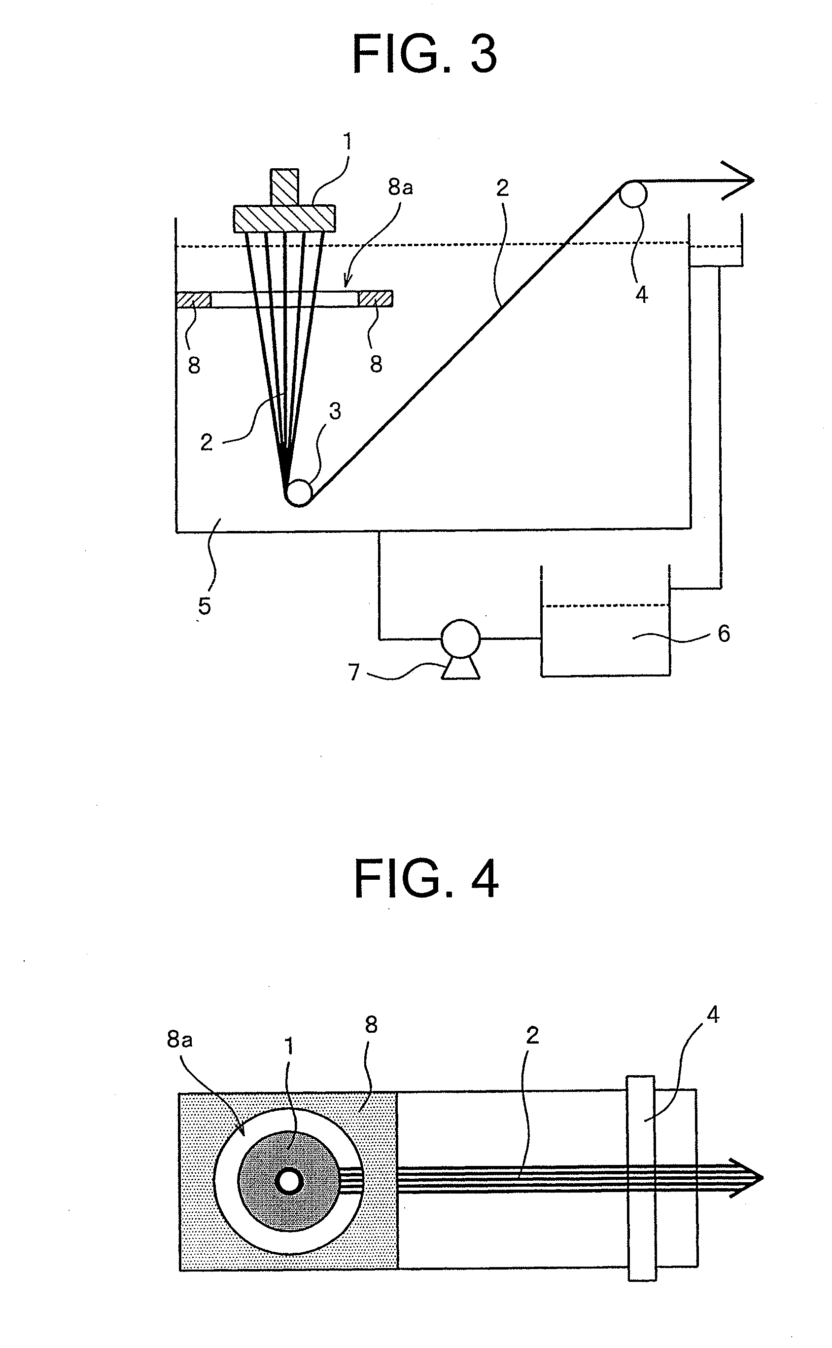
[0100]As illustrated in FIGS. 8 and 9, the depth of the horizontal flow straightening plate from the liquid surface was 100 mm, the distance between the outer periphery of the running yarn and the horizontal flow straightening plate was 35 mm, and the material of the horizontal flow straightening plate was a wire mesh manufactured by Kansai Wire Netting Co., Ltd. (120 mesh, a line diameter of 0.08 mm, a mesh size of 0.132 mm, and a material: SUS304). A stock solution for spinning was prepared at the same condition as Example 1 and the spinning was performed by following the same operations except that the material of the vertical flow straightening plate between the spinneret and the taking-up side guide is a wire mesh manufactured by Kansai Wire Netting Co., Ltd. (30 mesh, a line diameter of 0.18 mm, a mesh size of 0.67 mm, and a material: SUS304). The results obtained from the vibration state of the coagulating liquid surface and the observation by an electron microscope of a cros...
PUM
| Property | Measurement | Unit |
|---|---|---|
| Length | aaaaa | aaaaa |
| Fraction | aaaaa | aaaaa |
| Fraction | aaaaa | aaaaa |
Abstract
Description
Claims
Application Information
 - R&D
- Intellectual Property
- Life Sciences
- Materials
- Tech Scout
- Unparalleled Data Quality
- Higher Quality Content
- 60% Fewer Hallucinations
Browse by: Latest US Patents, China's latest patents, Technical Efficacy Thesaurus, Application Domain, Technology Topic, Popular Technical Reports.
© 2025 PatSnap. All rights reserved.Legal|Privacy policy|Modern Slavery Act Transparency Statement|Sitemap|About US| Contact US: help@patsnap.com