System and method for automated, range-based irrigation

a range-based, automatic technology, applied in the direction of process and machine control, instruments, electric devices, etc., can solve the problems that the irrigation system has not been tightly monitored or controlled historically, and achieve the effect of reducing water waste, efficient modification, and delivering water more effectively

Inactive Publication Date: 2014-08-21
BANYAN WATER
View PDF3 Cites 121 Cited by
  • Summary
  • Abstract
  • Description
  • Claims
  • Application Information

AI Technical Summary

Benefits of technology

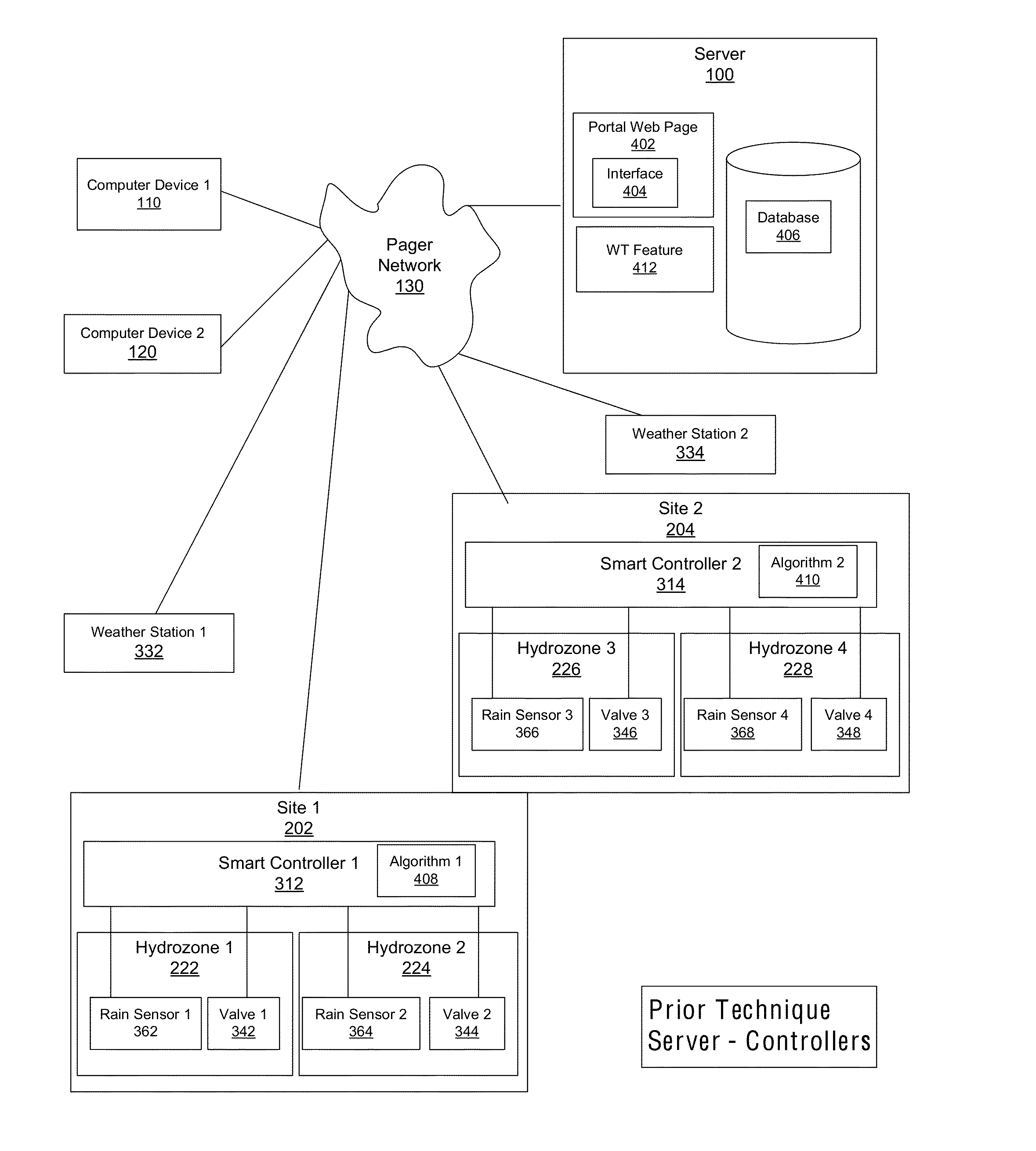
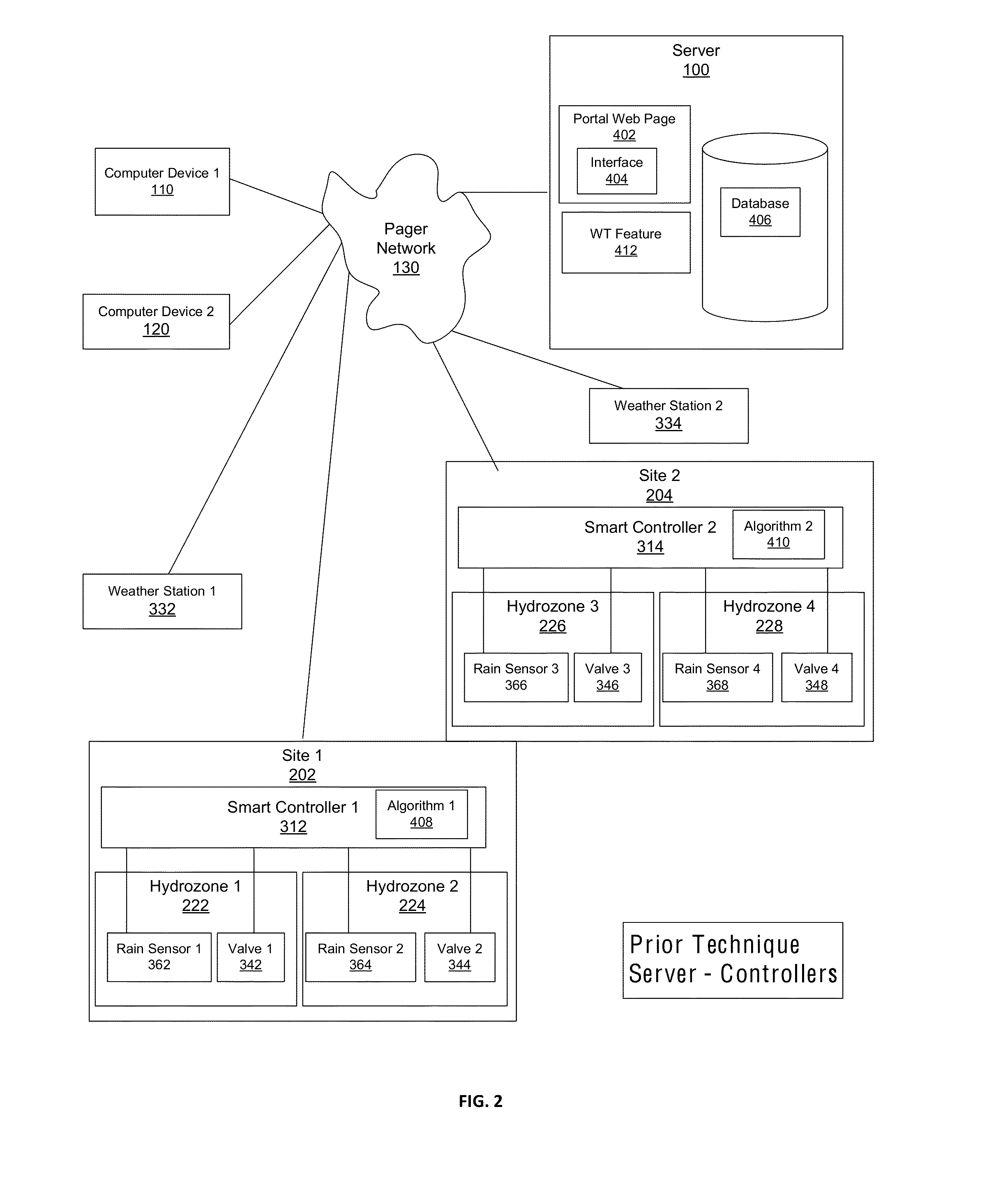
[0023]These systems have serious disadvantages, primarily because they are not sufficiently precise enough in the environmental data they collect and the calculations they make for irrigating specific sites. For example, they typically do not monitor or collect the actual volume of water that was applied to an area from a previously generated schedule and these systems do not measure and utilize effective rainfall in the—preventing the generation of an accurate new schedule. These types of irrigation control systems make a unilateral irrigation decision; they decide to irrigate for all or none of the irrigation zones, even though certain zones may not require irrigation. Therefore, these types of systems can only estimate the actual irrigation requirement and apply more water than is required across the multiple irrigation zones they manage. In addition, they typically use prior-day ET for their calculations of daily schedule modifications, although weather conditions may change dramatically not only from day to day but from moment to moment.
[0024]They also do not typically identify microclimates within zones sufficiently to efficiently modify pre-set schedules for special requirements in the microclimate. There typically is a water window of only so much water capacity per day in a given area, so that in some cases it would be more efficient to irrigate only those zones that have the greatest need based on the microclimate.
[0025]Another major problem is that these systems typically attempt to calculate a daily replacement net irrigation requirement for a zone, based on basic site and environmental factors, rather than calculate an optimal range of soil moisture. Plants actually do better within cycles of wetness and dryness in an appropriate range to cycle air through the soil root zone than they do when kept constantly at a single amount. For example, the Water Management Committee of The Irrigation Association has developed, adopted and publicized “Landscape Irrigation Scheduling and Water Management,” March 2005, which acknowledges the best methods of plant irrigation by watering to a management-defined depletion level (MAD).
[0026]As a result of these limitations, although these systems may deliver water more effectively to a given zone than clock-based systems do, they are still only focused to a limited degree on reducing water waste and optimizing irrigation water, which typically makes them more expensive to operate than is possible.
[0027]Moreover, these products typically have complicated, difficult-to-use interfaces, which makes them often complex to program, update, and manage and difficult to evaluate for return on investment. For example, decision-making controllers that themselves calculate water requirements and regulate irrigation may need to be updated at times. This updating will typically need to be done at the sites rather than at a central location, which is time consuming, laborious, and expensive. Smart controllers may offer an ability to update their firmware remotely; however, because the algorithms for their processes reside in the controllers, the controllers will always be difficult to update easily and efficiently.
[0028]In addition, these systems do not typically monitor the actual flow of water at a site. Instead, they irrigate a site based on a calculation of the system's flow rate from a fixed point in time.

Problems solved by technology

As mentioned above, irrigation systems have not historically been tightly monitored or controlled despite increasing costs and scarcity of the resources such as irrigation water.

Method used


Image

  • System and method for automated, range-based irrigation
  • System and method for automated, range-based irrigation
  • System and method for automated, range-based irrigation

Examples


example 1

Area Supervisor (AS)

[0340]An A.S. is in charge of monitoring the status and condition of clients C1, C2, and C3, plus property P1 of client C8. For this, he must do the following:[0341]Notify clients of any detected leaks;[0342]Send notices to irrigation contractors to make repairs on any valves that are stuck open, or closed;[0343]Determine that the appropriate amounts of water are being applied to each zone.[0344]Watch the total water use for the month, and compare this to historical water use, to gauge and / or alert his boss and / or clients as to potential overages for the month; and[0345]Look for any errors that may have occurred in the system during hours or days when no one is watching the system, and alert the appropriate people.

[0346]Monday morning the AS runs a copy of the dashboard 418, shown in FIG. 6, from his office computer 110. He opens the login screen and enters his user name and password. The dashboard 418 loads up, displaying his last saved layout.

[0347]To check for...

example 2

Field Assistant Operator (FAO)

[0354]A FAO helps people at the irrigation sites, such as clients, property managers, and landscape maintenance field personnel, who call in to perform tasks on the site. The FAO is called numerous times by various users, and she may be asked to:[0355]Operate field valves;[0356]Measure water flow; and[0357]Help callers locate physical entities within their sprawling landscape (such as controllers, zone valves, flow meters).

[0358]The FAO has two Dashboard Windows open on her multi-monitor computer system 120, shown in FIG. 6. The dashboard 418 on the left monitor is open to the Manual Operations module docked to the top, with the Log View module docked bottom left, and the Flow Meter Module docked bottom right.

[0359]When a user for client C1 calls in to open hydrozone 3 on their property P2, she selects the Manual Operations module, navigates to property P2, highlights the Zone Valve in the list of displayed valves, right-clicks and selects “Open . . . ”...

embodiment

Description of Embodiment

Environmental Credits Business Model

[0370]Another aspect of the invention is the opportunity to rapidly deploy improved control systems to save water for a community. In this example, a first entity such as an oil and gas producer may be depleting a resource such as groundwater. That entity can offset the use of the groundwater by sponsoring a water-savings program for a second entity, for example in exchange for the market value of the resource. In one example, the first entity contracts with a vendor to deploy the vendor's irrigation management systems for the second entity. The vendor installs and monitors the systems and measures the volume of water savings. This volume is then “credited” to the first entity to offset the waste of groundwater. For example, the first entity can utilize the water savings at the second entity as an offset of water overuse on the first entity's own project, or for an environmental stewardship advertisement campaign.

[0371]Thi...


PUM


Abstract

A centralized irrigation system provides decision-making or non-decision-making controllers in combination with a client server architecture that employs range-based irrigation algorithms for monitoring and control. Range-based control strategies determine a total volumetric water holding capacity for a volume of soil and a range of desirable soil moisture in a root zone, and compare a calculated root zone soil moisture to that range in order to determine the volume of water to be applied during an irrigation event. The system permits a shared-savings business model where the vendor provides a system and the customer only pays the vendor a portion of the savings obtained by using the system.

Description

RELATED APPLICATIONS[0001]This is a Continuation-in-part application of U.S. patent application Ser. No. 12 / 717,621 filed on Mar. 4, 2010 which is a Divisional application of U.S. patent application Ser. No. 12 / 506,614 which is a Continuation-in-part application of U.S. application Ser. No. 11 / 451,037 filed on Jun. 2, 2006.FIELD OF THE INVENTION[0002]The present invention relates generally to the field of the computerized monitoring and control of irrigation, and more particularly to a system and method that provide range-based soil moisture management calculations and irrigation decision algorithms at a cloud-based computer server, using both non-decision-making and decision-making programmable logic controllers in combination with a client server architecture that uses enhanced modeling for monitoring, analysis, and control and localized environmental data and forecasting.BACKGROUND OF THE INVENTION[0003]Water management through the computerized monitoring and control of irrigatio...

Claims


Application Information

Patent Timeline
Patent Type & Authority Applications(United States)
IPC IPC(8): A01G25/16G06Q50/06
CPCG06Q50/06A01G25/16A01G25/167G06Q10/0631G06Q50/02
Inventor COOK, KENNETH W.
Owner BANYAN WATER
Why Eureka
Try Eureka