
System and method for providing a command buffer in a memory system

a memory system and command buffer technology, applied in the computer field, can solve problems such as communication bottlenecks

Active Publication Date: 2014-08-21
RAMBUS INC
View PDF7 Cites 63 Cited by
  • Summary
  • Abstract
  • Description
  • Claims
  • Application Information

AI Technical Summary

Benefits of technology

This patent describes a system and method for interfacing with a co-processor or input / output device. The system receives a command from a host system and stores it in a buffer for checking if it is complete. If it is, the system provides the command to a command buffer. The command buffer includes a field that specifies the entry point of the command within the buffer. This helps the system to efficiently process commands and transfer them to the memory device. The technical effects of this patent include improved performance and reliability of the system, as well as improved data transfer efficiency between the host system and the memory device.

Problems solved by technology

However, the lower bandwidths supported by I / O buses often create communication bottlenecks for I / O or co-processing applications that are able to operate at much faster speeds.

Method used


Image

  • System and method for providing a command buffer in a memory system
  • System and method for providing a command buffer in a memory system
  • System and method for providing a command buffer in a memory system

Examples


Embodiment Construction

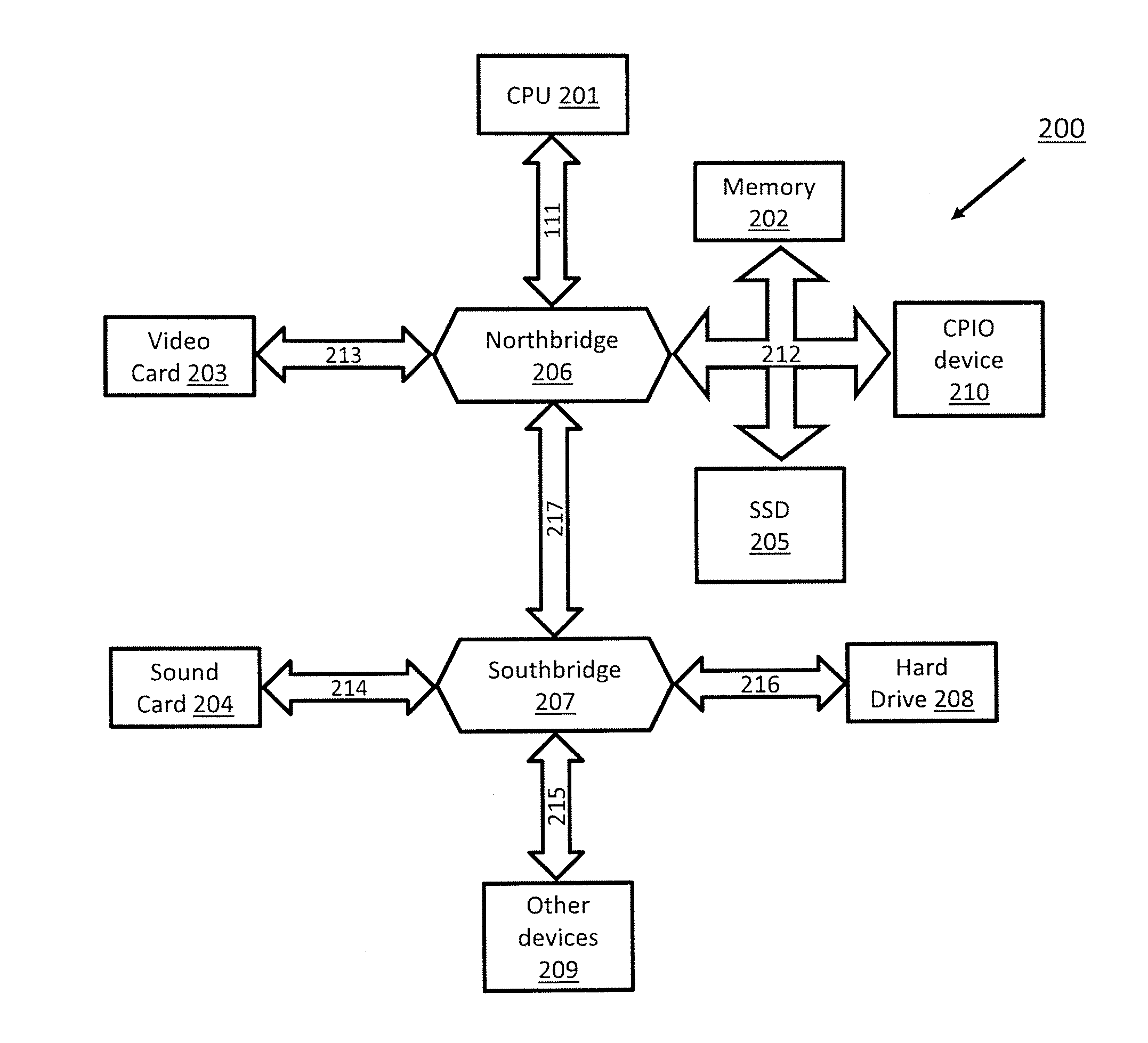
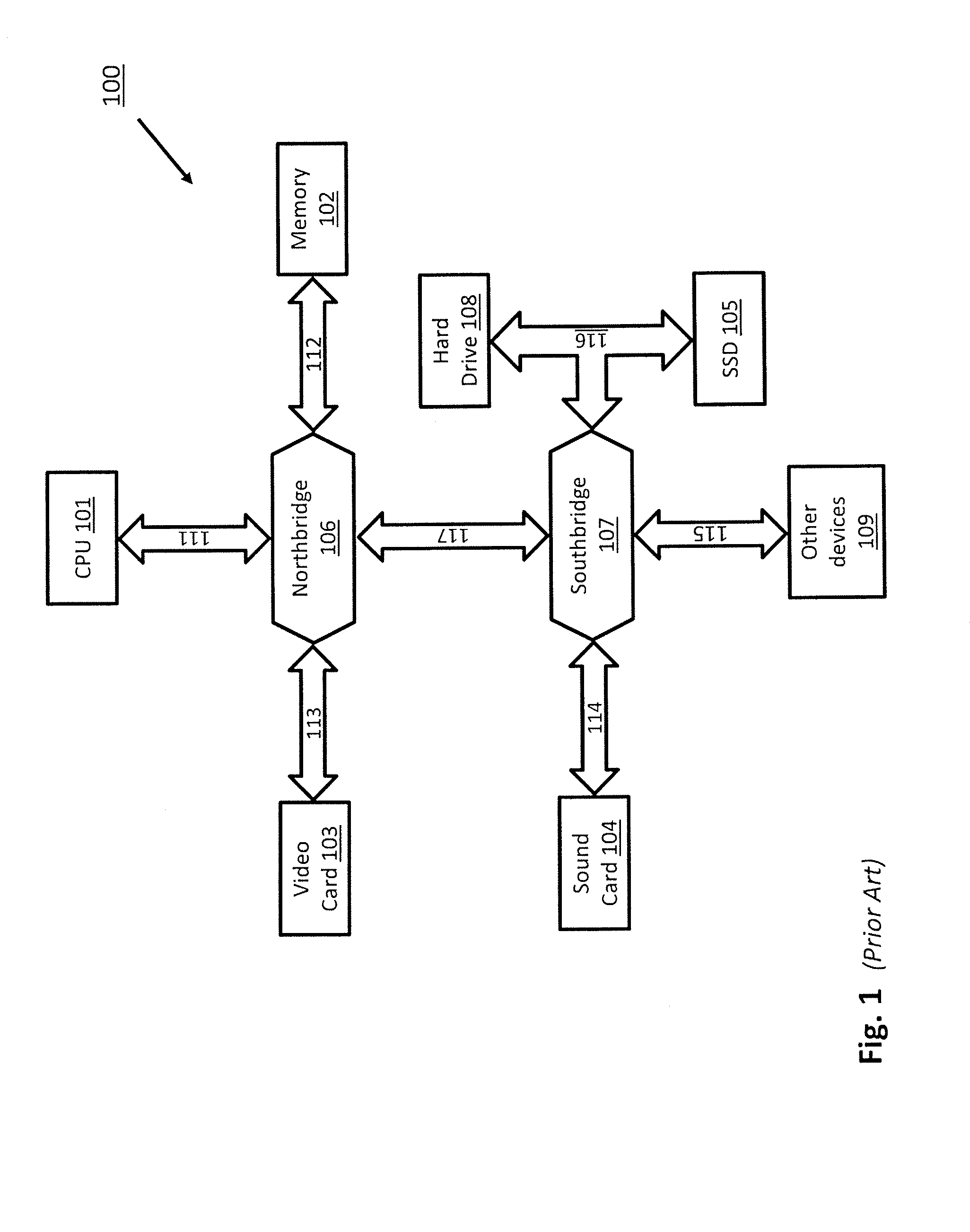
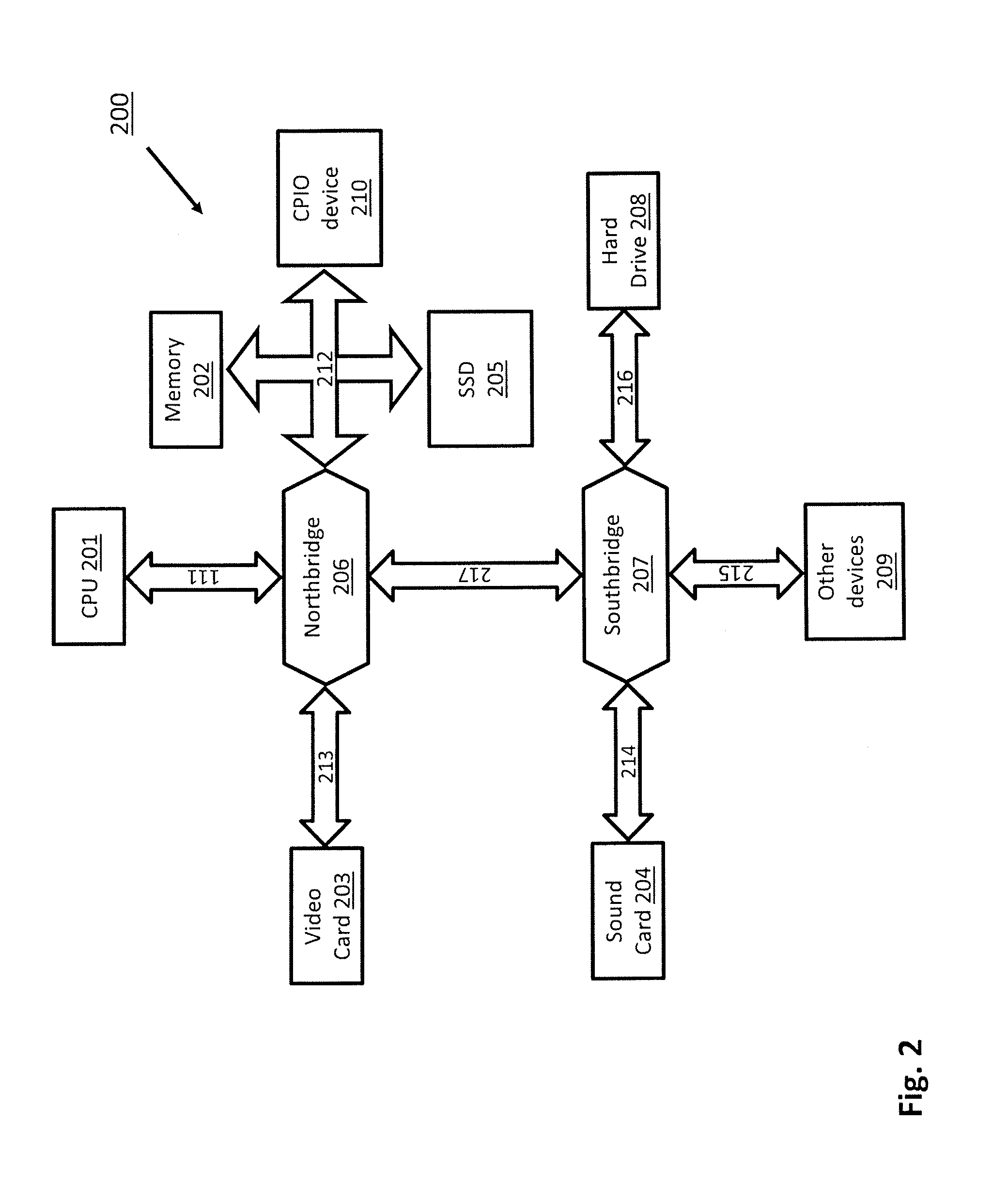
[0042]FIG. 1 illustrates a block diagram of a typical prior art computer architecture that connects co-processors or I / O (CPIO) devices via I / O buses. A computer system 100 typically includes a CPU (central processing unit) 101, a main memory unit 102 (e.g., one or more DRAM (dynamic random access memory) modules), and CPIO devices including a video card 103, a sound card 104, a hard drive 108, and a solid state drive (SSD) 105. These components are connected together via buses on a motherboard (not shown). As illustrated, CPU 101, main memory unit 102, and video card 103 are connected via their respective buses, 111, 112 and 113, to a northbridge 106. A northbridge 106 is traditionally a chip in the chipset of the motherboard that connects high speed buses, including the FSB (front-side bus) 111, the main memory bus 112, and the PCI-E (peripheral component interconnect express) bus 113.

[0043]Slower buses, including the PCI bus 114, the USB (universal serial bus) 115, and the SATA (...


PUM


Abstract

A system for interfacing with a co-processor or input / output device is disclosed. According to one embodiment, the system is configured to receive a command from a host memory controller of a host system and store the command in a command buffer entry. The system determines that the command is complete using a buffer check logic and provides the command to a command buffer. The command buffer comprises a first field that specifies an entry point of the command within the command buffer entry.

Description

COPYRIGHT NOTICE[0001]A portion of the disclosure of this patent document contains material that is subject to copyright protection. The copyright owner has no objection to the facsimile reproduction by anyone of the patent document or the patent disclosure, as it appears in the Patent and Trademark Office patent files or records, but otherwise reserves all copyright rights whatsoever.CROSS-REFERENCE TO RELATED APPLICATIONS[0002]The present application is a continuation-in-part of U.S. patent application Ser. No. 14 / 247,162, filed Apr. 7, 2014, entitled “System and Method of Interfacing Co-Processors and Input / Output Devices Via a Main Memory System,” which is a continuation of U.S. patent application Ser. No. 13 / 303,048 filed on Nov. 22, 2011, now U.S. Pat. No. 8,713,379, issued Apr. 29, 2014, entitled “System and Method of Interfacing Co-Processors and Input / Output Devices Via a Main Memory System,” which claims the benefit of and priority to U.S. Provisional Patent Application No...

Claims


Application Information

Patent Timeline
Patent Type & Authority Applications(United States)
IPC IPC(8): G06F3/06
CPCG06F3/0656G06F3/0604G06F3/065G06F3/0683G06F3/0659H03M13/05G06F13/1673G06F11/1008G09C1/00H04L9/3073H04L2209/125G06F21/71G06F21/85G06F12/1027
Inventor TAKEFMAN, MICHAEL L.AMER, MAHERBADALONE, RICCARDO
Owner RAMBUS INC
Learn More