
Wireless charging system

a charging system and wireless technology, applied in the direction of transportation and packaging, transmission, sustainable buildings, etc., can solve the problems of reducing the charging efficiency, increasing the loss amount following the increase of the charging current, and high temperature of the lithium ion battery, so as to improve the charging efficiency

Inactive Publication Date: 2014-08-28
RENESAS ELECTRONICS CORP
View PDF4 Cites 10 Cited by
  • Summary
  • Abstract
  • Description
  • Claims
  • Application Information

AI Technical Summary

Benefits of technology

The patent text is about a problem with portable electronic devices that use secondary batteries. Increasing the battery capacity and charging speed can cause the temperature of the device to increase, which in turn can lower the charging efficiency and elongate the charging time. The problem is that when the device uses 1:1 wiring ratio for coils, the same current flows into both the primary and secondary coils, which causes more loss and temperature increase. The technical effect of this patent text is to provide a solution to reduce the temperature increase and improve the charging efficiency of portable electronic devices that use secondary batteries.

Problems solved by technology

Charging technology using such a wireless charging system as described above, however, has the following problems according to findings by the inventor.
However, when charging current is increased, a loss amount following the increase of charging current is also increased.
Problematically, influences of the temperature increase the temperature of the lithium ion battery high, lower the charging efficiency, and elongate charging time.

Method used


Image

  • Wireless charging system
  • Wireless charging system
  • Wireless charging system

Examples


first embodiment

[0034]

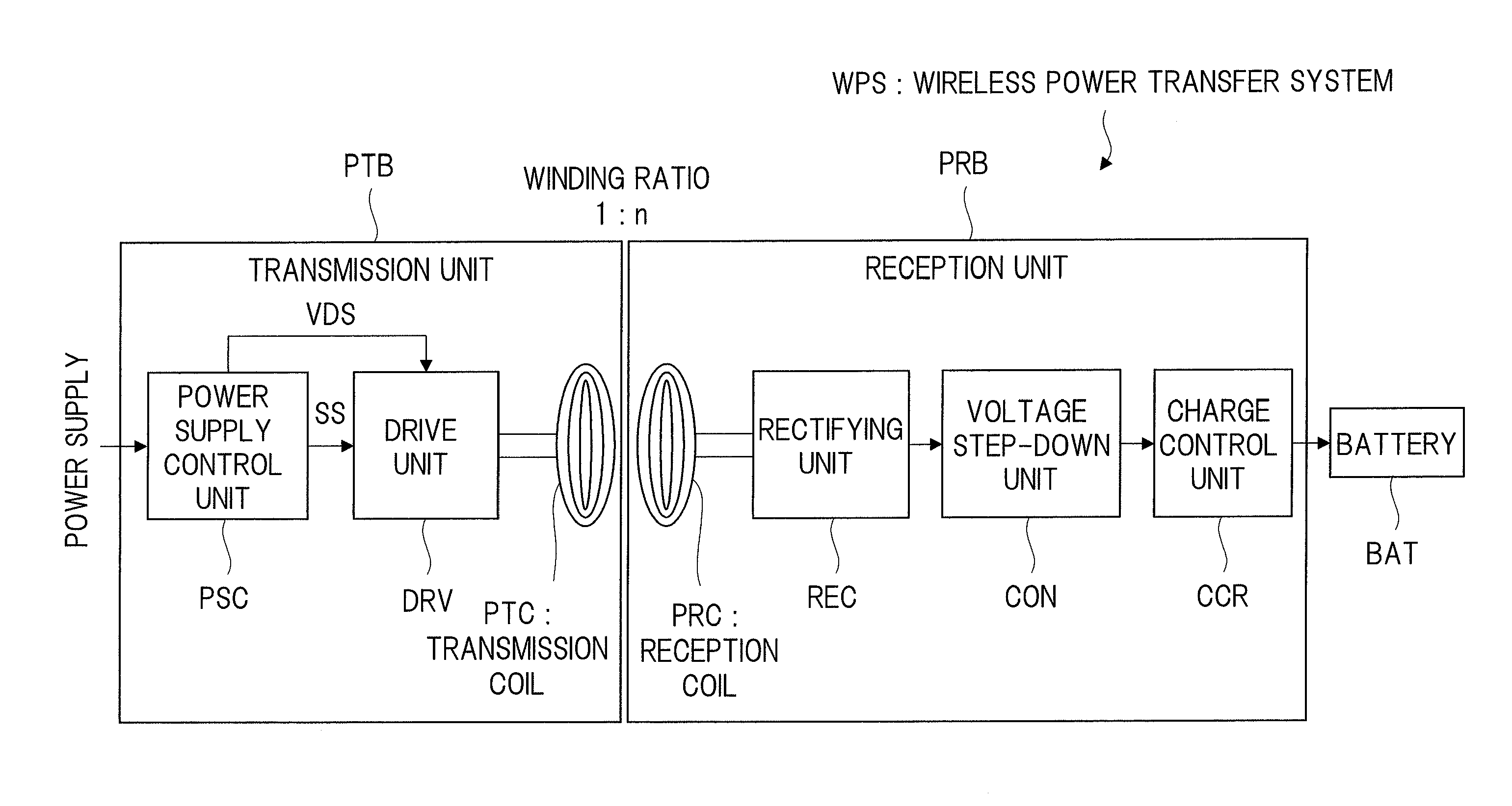
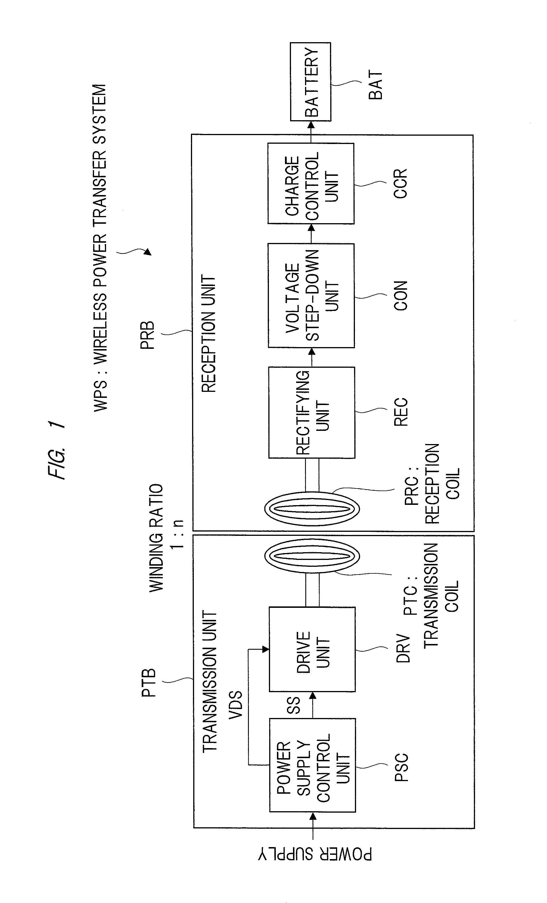
[0035]A summary of the embodiments is a wireless charging system (wireless charging system WPS) having a power transmission unit (transmission unit PTB) and a power reception unit (reception unit PRB). The power transmission unit transmits power, and the power reception unit receives the power transmitted from the power transmission unit in a non-contact manner and supplies the power to a reception-side load (battery BAT).

[0036]The power transmission unit has a transmission coil (transmission coil PTC) for generating a magnetic field based on an alternating voltage applied thereto. The power reception unit has a reception coil (reception coil PRC), a rectifying unit (rectifying unit REC), and a voltage step-down unit (voltage step-down unit CON).

[0037]A winding ratio of the transmission coil and the reception coil is 1:n. Moreover, n is an integer larger than 1.

[0038]Hereinafter, based on the summary described above, embodiments will be described in detail.

[0039]

[0040]FIG. 1 i...

second embodiment

[0093]In a second embodiment, another specific configuration example of the wireless charging system WPS in FIG. 1 will be described.

[0094]

[0095]FIG. 6 is an explanatory diagram illustrating an example of a configuration in a wireless charging system of a constant voltage type according to the second embodiment.

[0096]In this case, a wireless charging system WPS steps down a direct voltage obtained by a rectification by a rectifying unit REC to a voltage level at a substantially constant level previously set and outputs and supplies the direct voltage to a charge control unit CCR. This wireless charging system WPS of the constant voltage type is composed of a transmission unit PTB and a reception unit PRB as illustrated in FIG. 6. A configuration of the transmission unit PTB is same as that of the transmission unit PTB in FIG. 1 of the first embodiment.

[0097]In addition, in the configuration of the reception unit PRB, as the voltage step-down unit CON in FIG. 1 of the first embodimen...

third embodiment

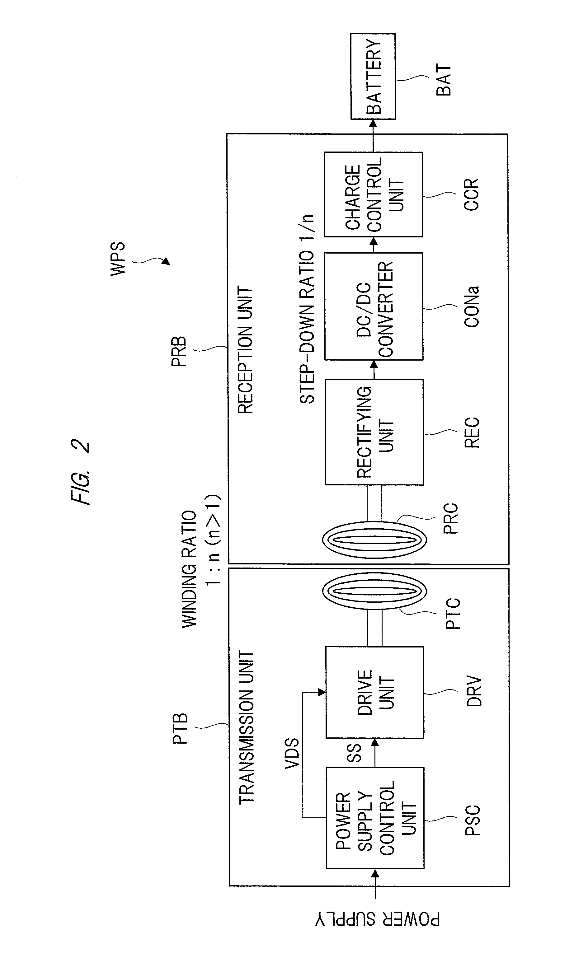
[0107]In a wireless charging system according to a third embodiment, a voltage step-down unit (DC / DC converter CONa) for stepping down a direct voltage outputted from a rectifying unit steps down a voltage outputted from a rectifying unit to about 1−nth as large as the voltage.

[0108]Hereinafter, the third embodiment will be described in detail based on the summary described above.

[0109]

[0110]In the third embodiment, a detailed configuration of the wireless charging system of the constant-rate stepping down type in FIG. 2 of the first embodiment will be described.

[0111]FIG. 7 is an explanatory diagram illustrating an example of a configuration of the wireless charging system of the constant-rate stepping down type according to the third embodiment.

[0112]The wireless charging system WPS is, as illustrated in FIG. 7, composed of a transmission unit PTB and a reception unit PRB. The transmission unit PTB includes, in the same manner as the transmission unit PTB in FIG. 2, a power supply...


PUM


Abstract

A wireless charging system includes a power transmission unit for transmitting power and a power reception unit for receiving the power transmitted from the power transmission unit in a non-contact manner and supplying the power to a receiving load. The transmission unit includes a power transmission coil for generating a magnetic field based on an alternating voltage supplied. The power reception unit includes a power reception coil for generating an induction voltage by electromagnetic induction from the magnetic field generated by the power transmission coil, a rectifying unit for rectifying and smoothing the induction voltage generated by the power reception coil, and a voltage step-down unit for stepping down a direct voltage outputted from the rectifying unit. A winding ratio of the power transmission coil and the power reception coil is 1:n where n is an integer larger than 1.

Description

CROSS-REFERENCE TO RELATED APPLICATION[0001]The present application claims priority from Japanese Patent Application No. 2013-039940 filed on Feb. 28, 2013, the content of which is hereby incorporated by reference into this application.TECHNICAL FIELD OF THE INVENTION[0002]The present invention relates to a wireless charging system, and relates to technology applicable to wireless charging for, for example, mobile electronic devices.BACKGROUND OF THE INVENTION[0003]In recent years, for some of portable electronic devices such as mobile phones and digital cameras, non-contact charging that is called wireless charging via electromagnetic induction can be used.[0004]As such a wireless charging, for example, a wireless charging system of electromagnetic induction type has been known, which is defined by the protocols of the Qi standard established by the Wireless Power Consortium (WPC) which is an industry group related to wireless charging technology.[0005]This kind of wireless chargin...

Claims


Application Information

Patent Timeline
Patent Type & Authority Applications(United States)
IPC IPC(8): H02J7/02H02J7/00
CPCH02J7/025H02J50/10H02J7/00712H02J50/12H04B5/24H04B5/79Y02B40/00
Inventor ENDO, TAKEFUMI
Owner RENESAS ELECTRONICS CORP
Learn More