Method and detector of loudspeaker diaphragm excursion

a detector and diaphragm technology, applied in the direction of transducer protection circuits, electrical equipment, etc., can solve the problems of high power consumption of digital signal processors executing model based estimate and/or control algorithms, complex model based approaches, and mechanical damage of various kinds, so as to achieve reliable and convenient protection

Active Publication Date: 2014-08-28
ANALOG DEVICES INT UNLTD
View PDF21 Cites 31 Cited by
  • Summary
  • Abstract
  • Description
  • Claims
  • Application Information

AI Technical Summary

Benefits of technology

[0017]The composite drive signal supplied to the voice coil of the electrodynamic loudspeaker may advantageously be pulse modulated to take advantage of the high power-conversion efficiency of pulse modulated amplifiers. This pulse modulation may be accomplished by utilizing a switching type or class D type of output amplifier topology for example PDM or PWM output amplifiers. The latter types of class D amplifiers provide pulse density or pulse width modulation of the audio signal to generate the composite drive signal in modulated format. In the alternative, the output amplifier may comprise traditional non-switched power amplifier topologies like class A or class AB. An output impedance of the power amplifier is preferably smaller than the voice coil impedance of the intended or target loudspeaker(s) throughout the relevant audio frequency range, e.g. 20 Hz to 20 kHz. Hence, the skilled person will appreciate that the output impedance of the output amplifier may vary significantly depending upon impedance characteristics of the target electrodynamic loudspeaker(s) in question. In a number of useful embodiments of the invention, the output impedance of the output amplifier is smaller than 1.0Ω, such as smaller than 0.5Ω or 0.1Ω throughout the relevant audio frequency range. These ranges of relatively small output impedances minimize power dissipation in output devices / transistors of the output amplifier, in particular when coupled to low-impedance electrodynamic loudspeakers, e.g. loudspeakers with nominal impedance in a range between 2 and 8 ohms. The output impedance of the output amplifier is preferably also smaller than 1.0Ω, such as smaller than 0.5Ω, or 0.1Ω, at the frequency of the probe signal.
[0020]According to a preferred embodiment of the present methodology, the high-frequency probe signal is generated in digital format as a digital high-frequency probe signal and added to one of the digital audio signals at the intermediate sample rates or to the final digital audio signal to generate a composite drive signal in digital format. In a particularly advantageous variant of the latter embodiment, the high-frequency digital probe signal is added to a digital audio signal with intermediate sample rate at least two times higher than a frequency of the digital high-frequency probe signal. The up-sampling the first digital audio signal to the intermediate sample rate digital audio signal above the Nyquist frequency of the digital high-frequency probe signal before addition of the digital high-frequency probe signal is beneficial in numerous applications. This up-sampling operation allows an audio signal generator supplying the first digital audio signal to operate with a relatively low sampling frequency or rate e.g. 32 kHz despite the use of a relatively high frequency of the digital probe signal such as 40 kHz situated far above the Nyquist frequency of the first digital audio signal. The relatively low sampling frequency of the audio signal generator reduces its power consumption. The up-sampling of the first digital audio signal may for example be accomplished in the above-mentioned modulator portion of the class D amplifier without the expense of additional digital processing hardware and its associated power consumption. The skilled person will appreciate that various types of signal quantisation and noise shaping may be applied to the final digital audio signal and / or to the intermediate digital audio signals in a modulator portion of the class D amplifier.
[0025]In one embodiment, the high-frequency probe signal is added to the audio signal as an integral operation of a pulse modulation of the audio signal in a class D output amplifier. Hence, the high-frequency probe signal may be added to the audio signal by modulating the audio signal with a predetermined carrier frequency in a pulse modulated output amplifier such that the high-frequency probe signal is produced by carrier frequency components. The high-frequency probe signal therefore comprises the carrier frequency component of the pulse modulation. This type of carrier frequency components are inherently added to the drive signal supplied to the loudspeaker by class D output amplifiers despite certain output filters which may attenuate the level of these carrier frequency components. While this carrier frequency component is unwanted under many circumstances, this particular embodiment exploits the presence of the carrier frequency component to eliminate separate high-frequency probe signal generation. Hence, a separate digital or analog probe signal generator and corresponding signal combiner are both saved leading to a reduction of the complexity of the present loudspeaker excursion detector and corresponding methodology.
[0027]Hence, when the level of the audio signal falls below the predetermined threshold level the addition of the high-frequency probe signal may be interrupted. In this embodiment, the predetermined threshold level ensures the high-frequency probe signal is added only to the audio signal under conditions where the audio signal has sufficient level or amplitude to force the loudspeaker diaphragm close to, or above, its excursion limit. The interruption of the high-frequency probe signal may serve to minimise possible audible artifacts associated with the high-frequency probe signal, in particular if the high-frequency probe signal is placed in the audible frequency range. In the alternative, the level of the high-frequency probe signal may be attenuated with a certain factor e.g. 20 dB or more when the level of the audio signal falls below the predetermined threshold level.
[0040]The present excursion control system may advantageously function as a self-contained audio delivery system with integral loudspeaker excursion detection and control that can operate independently of any particular environment and application processor to provide reliable and convenient protection against excursion induced mechanical damage of the electrodynamic loudspeaker.

Problems solved by technology

Unless proper precautionary measures are taken, powerful amplifiers may force such high levels of drive currents into the voice coil that the diaphragm and voice coil assembly is driven beyond its maximum allowable peak excursion leading to various kinds of mechanical damage.
These attempts have often been based on complex non-linear models of the particular loudspeaker type in question.
Likewise, model based approaches require complex real-time computations on the non-linear loudspeaker model to estimate the actual excursion of the real operative loudspeaker.
Complex computations leads to high power consumption of a Digital Signal Processor executing the model based estimate and / or control algorithm which is particularly undesired for battery powered communication devices like smartphones etc.
The model parameters can furthermore be difficult to determine accurately and may vary over temperature, time and between individual loudspeaker samples of the same type.

Method used


Image

  • Method and detector of loudspeaker diaphragm excursion
  • Method and detector of loudspeaker diaphragm excursion
  • Method and detector of loudspeaker diaphragm excursion

Examples


Embodiment Construction

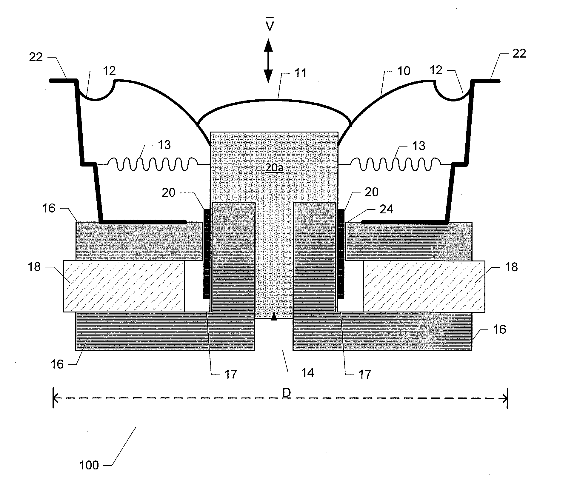
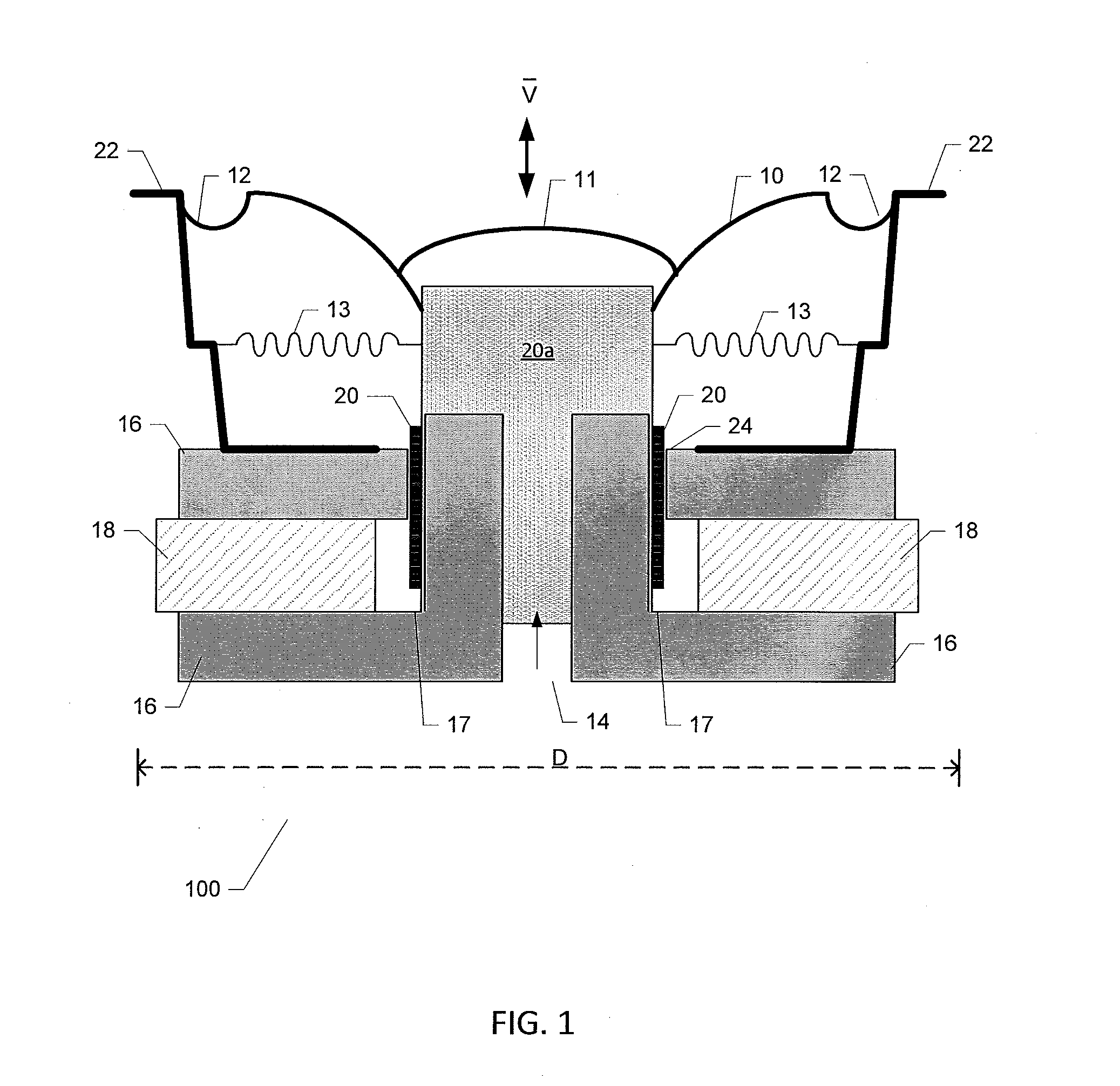
[0049]FIG. 1 is a schematic illustration of a typical electrodynamic loudspeaker 100 for use in various types of audio applications. The skilled person will appreciate that electrodynamic loudspeakers exist in numerous shapes and sizes dependent on the intended type of application. The electrodynamic loudspeaker 100 used in the below described methodologies and devices for loudspeaker excursion detection and control has a diaphragm diameter, D, of approximately 6.5 inches, but the skilled person will appreciate that the present invention is applicable to virtually all types of electrodynamic loudspeakers, in particular to miniature electrodynamic loudspeaker for sound reproduction in portable terminals such as mobile phones, smartphones and other portable music playing equipment. The maximum outer dimension D such miniature electrodynamic loudspeakers may lie between 6 mm and 30 mm.

[0050]The electrodynamic loudspeaker 100 comprises a diaphragm 10 fastened to a voice coil former 20a....


PUM


Abstract

The present invention relates in one aspect to a method of detecting diaphragm excursion of an electrodynamic loudspeaker. The method comprises steps of generating an audio signal for application to a voice coil of the electrodynamic loudspeaker and adding a high-frequency probe signal to the audio signal to generate a composite drive signal. The method further comprises a step of applying the composite drive signal to the voice coil through an output amplifier and detecting a modulation level of a probe signal current flowing through the voice coil.

Description

[0001]The present invention relates in one aspect to a method of detecting diaphragm excursion of an electrodynamic loudspeaker. The method comprises steps of generating an audio signal for application to a voice coil of the electrodynamic loudspeaker and adding a high-frequency probe signal to the audio signal to generate a composite drive signal. The method further comprises a step of applying the composite drive signal to the voice coil through an output amplifier and detecting a modulation level of a probe signal current flowing through the voice coil.BACKGROUND OF THE INVENTION[0002]The present invention relates to a method of detecting diaphragm excursion or displacement of electrodynamic loudspeakers and a corresponding loudspeaker excursion detector. Methodologies and devices for detecting diaphragm excursion of electrodynamic loudspeakers are highly useful for numerous purposes for example in connection with diaphragm excursion control or limitation. Diaphragm excursion con...

Claims


Application Information

Patent Timeline
Patent Type & Authority Applications(United States)
IPC IPC(8): H04R29/00
CPCH04R29/003H04R3/007
Inventor ADAMS, ROBERTBERTHELSEN, KIM SPETZLER
Owner ANALOG DEVICES INT UNLTD
Why Eureka
Try Eureka