
Coated substrates for use in catalysis and catalytic converters and methods of coating substrates with washcoat compositions

a technology of catalytic converters and substrates, applied in the field of catalytic converters, can solve the problems of reducing the efficiency of pgm catalysts, releasing pollutants into the environment, and reducing the efficiency of catalytic converters over time, so as to improve the performance of the emission control system, reduce the emission of one, and reduce the light-off temperature

Inactive Publication Date: 2014-08-28
SDC MATERIALS +1
View PDF4 Cites 36 Cited by
  • Summary
  • Abstract
  • Description
  • Claims
  • Application Information

AI Technical Summary

Benefits of technology

The disclosed catalysts and washcoats can reduce the light-off temperatures of catalytic converters and, at the same time, use less or the same amount of platinum group metals compared to aged wet-chemistry methods. This results in improved performance and reduced costs of the emission control system. The coated substrates described in this patent can have a higher level of loading with platinum group metals and, even after a certain operation, still have lower light-off temperatures for carbon monoxide compared to these substrates made by wet-chemistry methods. The patent text also demonstrates that the coated substrates can achieve this while using less litany in the exhaust gas.

Problems solved by technology

A high light-off temperature is undesirable, as many vehicular trips are of short duration, and during the time required for the catalytic converter to reach its operating temperature (that is, the light-off temperature), pollutants must either be released untreated to the environment, or stored in the exhaust system until the light-off temperature is reached.
Even if pollutants are trapped effectively prior to light-off, the catalytic converter may not reach operating temperature if multiple successive short trips are made, and the zeolites used for storage may become saturated, again resulting in release of pollutants to the environment.
These PGM catalysts are a considerable portion of the cost of catalytic converters.
Commercially available catalytic converters also display a phenomenon known as “aging,” in which they become less effective over time; the light-off temperature starts to rise as the catalytic converter ages, and emission levels also start to rise.

Method used


Image

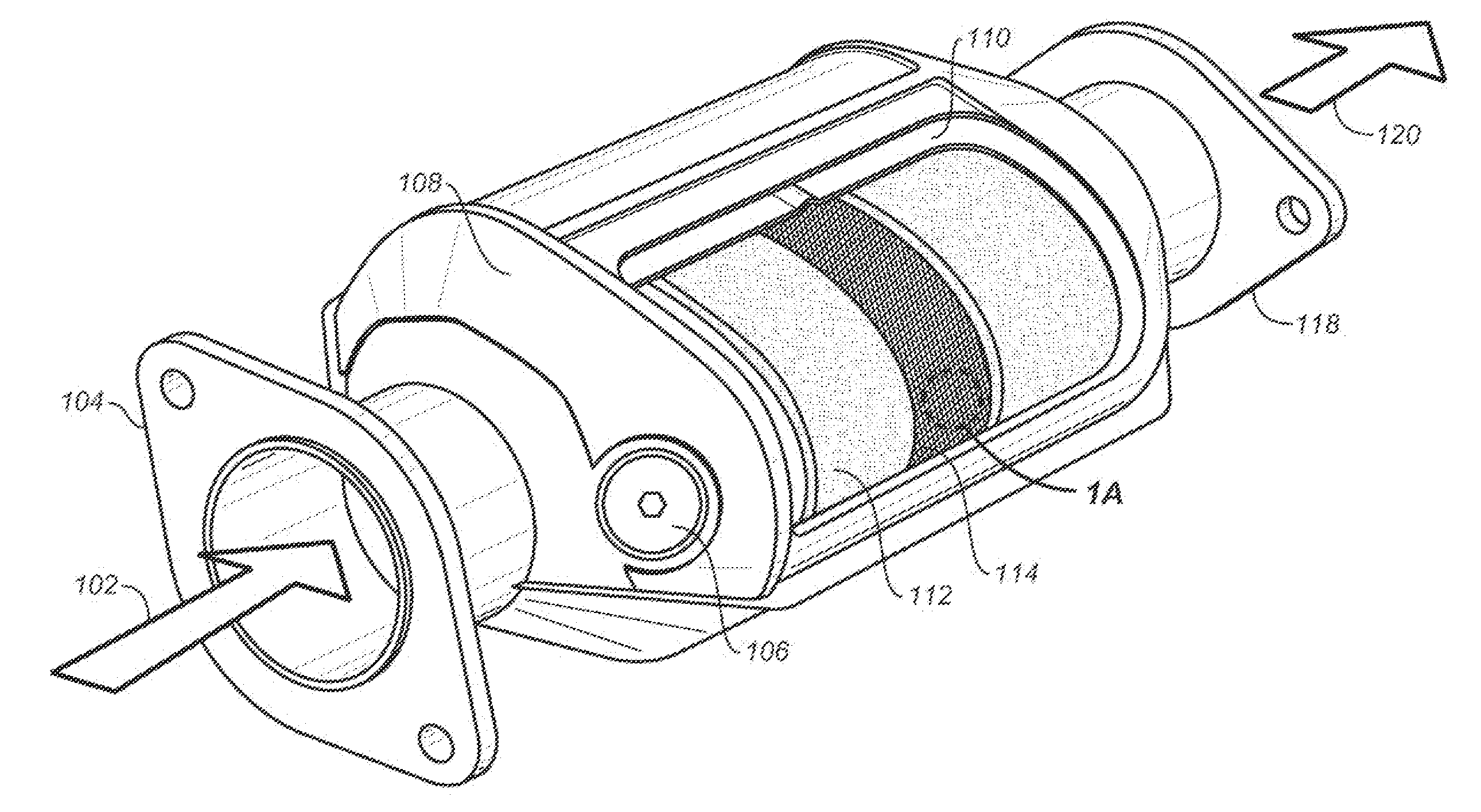
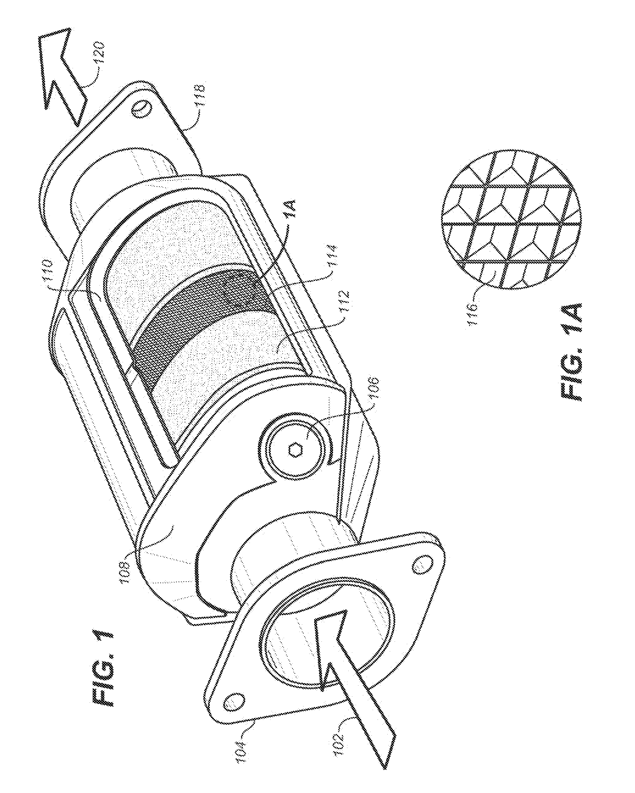
  • Coated substrates for use in catalysis and catalytic converters and methods of coating substrates with washcoat compositions
  • Coated substrates for use in catalysis and catalytic converters and methods of coating substrates with washcoat compositions
  • Coated substrates for use in catalysis and catalytic converters and methods of coating substrates with washcoat compositions

Examples


example 1

Substrate-Zeolite Particles-Catalytic Powder Configuration, or S-Z-C, Configuration: No Zeolites in Catalyst-Containing Washcoat

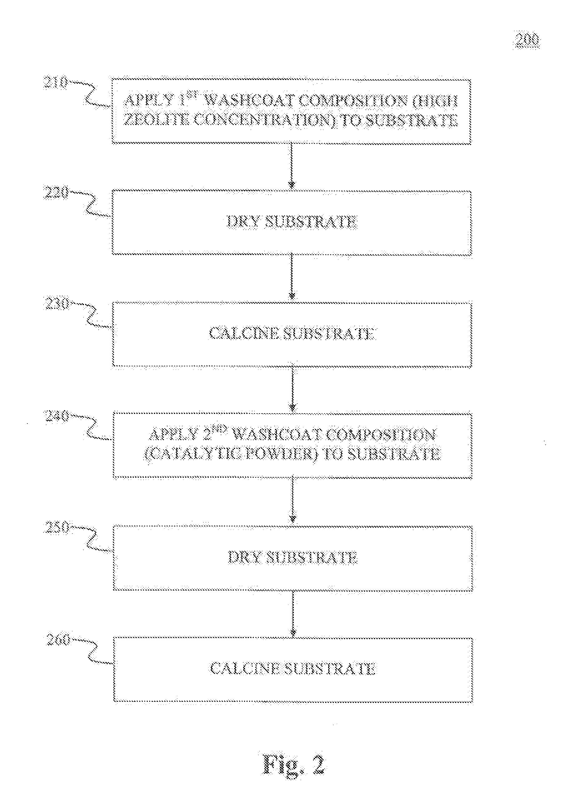
[0188](a) First Washcoat Composition: Approx. 70 g / l as follows:[0189]3% Boehmite[0190]80% Zeolites[0191]17% Porous alumina (MI-386 or the like)[0192](b) Second Washcoat Composition: Approx. 120 g / l as follows:[0193]3% Boehmite;[0194]5% Silica;[0195]92% NNm Powder (nano-particle on nano-particle on micro-particle), the powder that contains the PGM, i.e. the platinum group metals or precious metals.

[0196]Mix the washcoat ingredients from (a) with water and acetic acid and to adjust the pH to about 4. After adjusting the viscosity to the proper levels, the washcoat gets coated onto the substrate with an approximate layer thickness of 70 g / l. Excess washcoat is blown off and recycled. This first washcoat layer is then dried and calcined. Following this first washcoating step, a second washcoating step is performed: the ingredients from (b) are mixed with water...

example 2

Substrate-Zeolite Particles-Catalytic Powder Configuration, or S-Z-C, Configuration: Zeolites Present in Catalyst-Containing Washcoat

[0197](a) First Washcoat Composition: Approx. 70 g / l as follows:[0198]3% Boehmite[0199]80% Zeolites[0200]17% Porous alumina (MI-386 or the like)[0201](b) Second Washcoat Composition: Approx. 120 g / l as follows:[0202]3% Boehmite;[0203]5% Zeolites;[0204]92% NNm Powder (catalytic nano-particle on support nano-particle on support micro-particle), the powder that contains the PGM, i.e. the platinum group metals or precious metals.

[0205]The same procedure described in Example 1 is used to coat the substrate in this example.

example 3

Additional Example of Substrate-Zeolite Particles-Catalytic Powder, or S-Z-C, Configuration

[0206](a) First Washcoat Composition: 25 g / l to 90 g / l (approximately. 60 g / l or approximately 70 g / l preferred) as follows:[0207]2-5% Boehmite (about 3% preferred);[0208]60-80% Zeolites, such as 75-80% Zeolites (about 80% preferred);[0209]15-38% Porous alumina (MI-386 or the like), such as 15-22% Porous alumina (about 17% to about 22% preferred).[0210](b) Second Washcoat Composition: 50 g / l to 250 g / l (approximately 120 g / l preferred) as follows:[0211]2-5% Boehmite (about 3% preferred);[0212]0-20% Silica (about 5% preferred);[0213]40-92% catalytically active powder (about 92% preferred); and[0214]0-52% porous alumina (about 0% preferred).

[0215]The same procedure described in Example 1 is used to coat the substrate in this example. In another embodiment, 0-20% Zeolites are used instead of the 0-20% Silica (with about 5% being the preferred amount of Zeolite used).


PUM


Abstract

Disclosed are, inter alia, methods of forming coated substrates for use in catalytic converters, as well as washcoat compositions and methods suitable for using in preparation of the coated substrates, and the coated substrates formed thereby. The catalytic material is prepared by a plasma-based method, yielding catalytic material with a lower tendency to migrate on support at high temperatures, and thus less prone to catalyst aging after prolonged use. Also disclosed are catalytic converters using the coated substrates, which have favorable properties as compared to catalytic converters using catalysts deposited on substrates using solution chemistry. Also disclosed are exhaust treatment systems, and vehicles, such as diesel vehicles, particularly light-duty diesel vehicles, using catalytic converters and exhaust treatment systems using the coated substrates.

Description

CROSS-REFERENCE TO RELATED APPLICATIONS[0001]This patent application claims priority benefit of U.S. Provisional Patent Application No. 61 / 525,661 filed Aug. 19, 2011, and of U.S. Provisional Patent Application No. 61 / 652,098 filed May 25, 2012. The entire contents of those patent applications are hereby incorporated by reference herein.FIELD OF THE INVENTION[0002]The present invention relates to the field of catalysts. More specifically, the present invention relates to nano-particle catalysts, catalytic converter washcoats, and catalytic converters formed from such washcoats.BACKGROUND OF THE INVENTION[0003]A significant portion of pollutant gases emitted by internal combustion engines are produced when the engine is initially started (“cold-start”), but before the catalytic converter in the emissions system has warmed up to its operating temperature. In order to reduce harmful emissions during the cold-start phase, such as that of a light-duty diesel vehicle (for example, an auto...

Claims


Application Information

Patent Timeline
Patent Type & Authority Applications(United States)
IPC IPC(8): B01J29/068
CPCB01D53/944B01J2229/42B01D2255/1023B01D2255/2092B01D2255/30B01D2255/50B01D2255/9022B01D2255/912B01D2255/9155B01D2255/9202B01D2258/012B01D53/945B01J29/04B01J37/0244B01J37/0246B01J37/16B01J37/349B01J21/04B01J23/44B01J23/63B01J29/06B01J29/068B01J35/0013B01J35/0066B01J35/023B01J35/04B01J37/0018B01J37/0213B01D2255/1021B01J35/394B01J35/19B01J35/23B01J35/56B01J35/40
Inventor YIN, QINGHUAQI, XIWANGBIBERGER, MAXIMILIAN A.SARKAR, JAYASHIR
Owner SDC MATERIALS
Learn More