
Nasal implants and systems and methods of use

a technology for nasal implants and nasal arteries, applied in the field of nasal implants, can solve the problems of reducing the quality of life and affecting the health of individuals, and achieve the effect of increasing the flexibility of the implan

Active Publication Date: 2014-08-28
SPIROX INC
View PDF10 Cites 50 Cited by
  • Summary
  • Abstract
  • Description
  • Claims
  • Application Information

AI Technical Summary

Benefits of technology

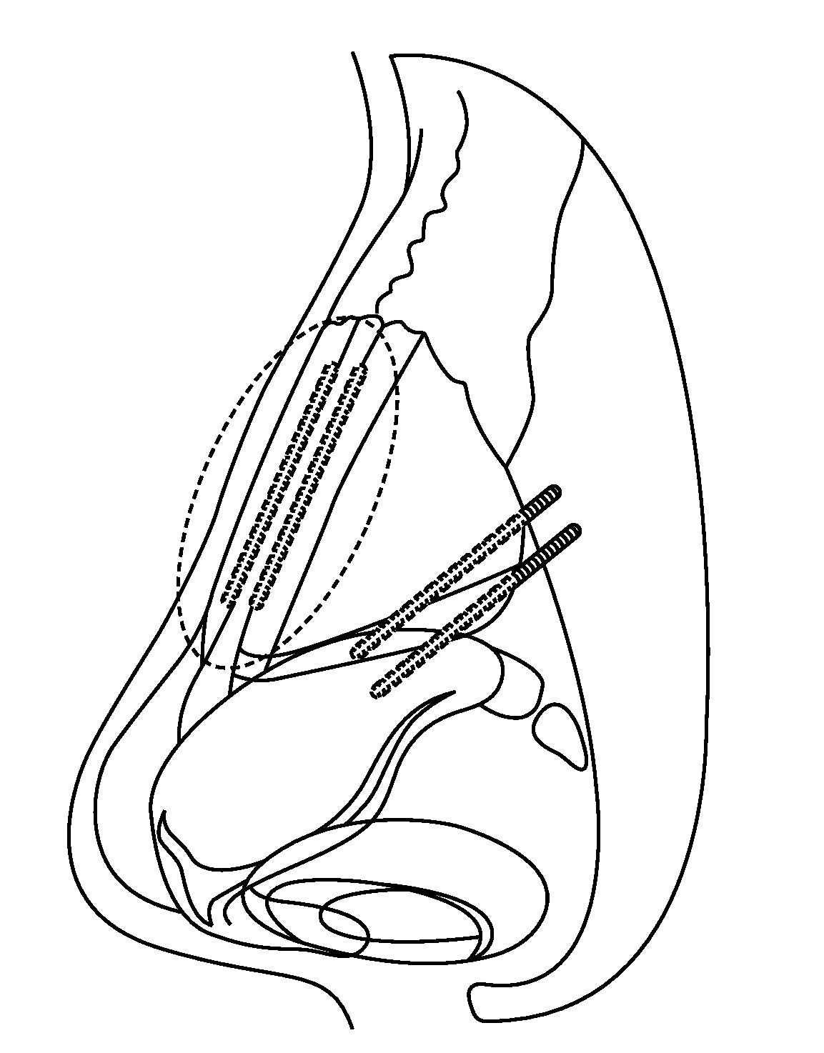
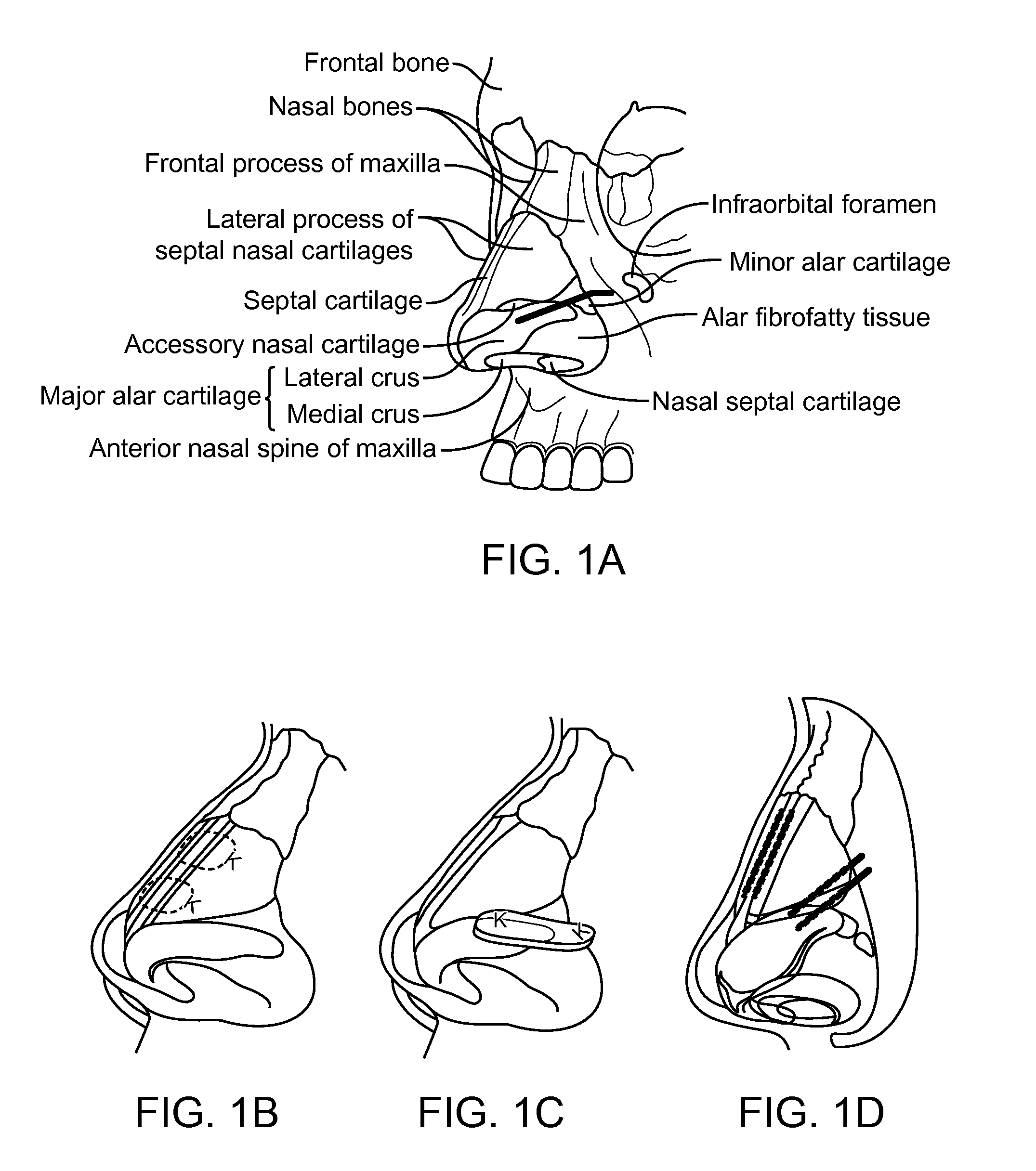
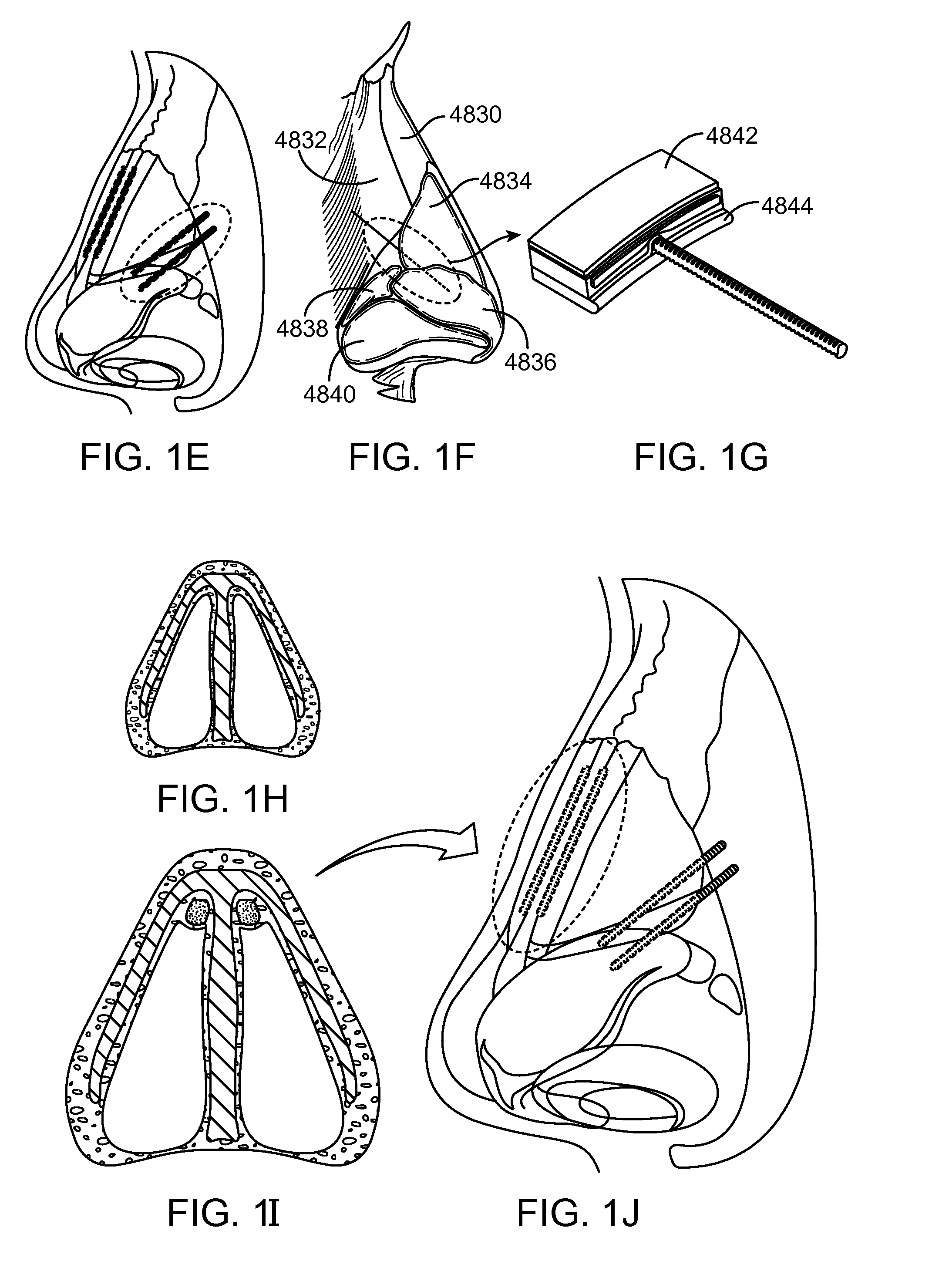
The patent describes implants and tools for placing them in a body, particularly in the nasal tissue. These implants can be used to support or repair nasal tissue, and some may provide a long-term solution for improved nasal function or cosmesis. The implants can be shaped in a pre- or shapeable manner and can be held in place using energy delivery and removal. The methods may involve delivering energy to the implant to increase its flexibility and then shaping it to a desired shape before removing the energy. The invention can be used in a minimally invasive procedure and may require only a local anesthetic. The implants can provide a long-term solution for nasal tissue support and can be shaped to support specific nasal functions or cosmetic concerns.

Problems solved by technology

The particular nasal anatomy of an individual may cause or contribute to various problems, such as cosmetic concerns, difficulty breathing, sleep apnea, or snoring, and impact an individual's health or reduce the quality of life.

Method used


Image

  • Nasal implants and systems and methods of use
  • Nasal implants and systems and methods of use
  • Nasal implants and systems and methods of use

Examples


example 1

[0211]Material samples testing Table 1 shows material property test results of candidate implants made into various shapes and sizes with the indicated inner diameter (ID) and outer diameter OD) from the indicated materials. The modulus of elasticity (E), cross-sectional inertia of the sample (I), and flexural rigidity (E•I) which represents the strength of the sample when bending, are indicated. The PLLA and PLLA-PGA samples were flexurally stronger than the other samples, presumably due to the strength of the PLLA and the rod shape of the PLLA-PGA sample. The PLLA-PDLA sample was weak in bending, presumably due to its thin-wall, tube shape. The PLLA-PCL sample was very flexible, presumably because it was in a glassy stage as its glass transition temperature is below room temperature; overall it did not behave like a typical solid material.

example 2

Table 2 Shows Moldability with Temperature and Brittleness

[0212]Testing performed on the material samples. Samples were cut to 15 mm length. Samples were tested at room temperature and heated to several temperatures in an oven and left to sit to ensure the materials were a consistent temperature throughout the sample. Each sample was tested by removing it from the oven and immediately bending it by hand to 90 degrees (if possible). Observations of how much force was required, whether the material held the shape, cool off time, and material brittleness were recorded and summarized.

example 3

[0213]An implantable sheet was cut and tested for fitting into a 16 gauge syringe. Samples fit through. When a scalpel is place accurately through the bridge trough, the sheet could be cut relatively easily. FIG. 53A and FIG. 53B show results from cutting an implantable sheet.


PUM

PropertyMeasurementUnit
outer diameteraaaaaaaaaa
lengthaaaaaaaaaa
lengthaaaaaaaaaa

Abstract

Described are implants for placing in a body, tools for delivering the implants, and systems and methods for using implants and tools for placing in a body and more particularly to nasal implants, tools for delivering nasal implants, and systems and methods for using such implants and tools. A tool may include a hand-held implant delivery device that cuts, holds, moves, orients, inserts, or shapes an implant. An implant may be a biodegradable, longitudinal implant that may be oriented for implantation by an implant delivery device.

Description

CROSS REFERENCE TO RELATED APPLICATIONS[0001]This application claims the benefit under 35 U.S.C. §119 of U.S. Patent Application No. 61 / 770,008 filed Feb. 27, 2013 and U.S. Patent Application No. 61 / 785,816 filed Mar. 14, 2013, the disclosures of which are incorporated herein by reference.INCORPORATION BY REFERENCE[0002]All publications and patent applications mentioned in this specification are herein incorporated by reference to the same extent as if each individual publication or patent application was specifically and individually indicated to be incorporated by reference.FIELD[0003]The present invention pertains to implants for placing in a body, tools for delivering the implants, and systems and methods for using implants and tools for placing in a body and more particularly to nasal implants, tools for delivering nasal implants, and systems and methods for using such implants and tools.BACKGROUND[0004]The particular nasal anatomy of an individual may cause or contribute to va...

Claims


Application Information

Patent Timeline
Patent Type & Authority Applications(United States)
IPC IPC(8): A61F5/08A61F2/18
CPCA61F5/08A61F2/186A61L27/18A61F2230/0008A61B17/3468A61B17/24C08L67/04A61F2/18A61L27/58A61L2430/34
Inventor SAIDI, IYAD S.ROSENTHAL, MICHAEL H.GONZALES, DONALD A.LOPER, J. CAMERONHADLEY, MARCUS A.INGRAM, JAMIE L.REN, CHENG Q.LUDDY, CHARLES P.MARUCCHI, LEON A.GRAY, BRUCE C.CARLTON, R. ANDREW
Owner SPIROX INC
Learn More