Signal reception multi-tuner system and corresponding method

Active Publication Date: 2014-09-04
INTERDIGITAL CE PATENT HLDG
View PDF12 Cites 0 Cited by
  • Summary
  • Abstract
  • Description
  • Claims
  • Application Information

AI Technical Summary

Benefits of technology

The invention is a system for reducing interference between two tuners in a device that receives signals. It uses a first tuner and a second tuner, each with its own local oscillator, to translate the frequency of a signal. The system also includes a demodulator. This helps to improve the quality of the received signals. The invention is simple to implement and can be used in electronic devices that have multiple tuners.

Problems solved by technology

Whatever the input architecture of a multi-tuner receiver there is a significant disadvantage.
Electromagnetic emissions exist between the tuners and can create interferences.
The problem of crosstalk occurs more specifically when two tuners are tuned onto the same conversion frequency, called LO (Local Oscillator).
This technique has the disadvantage of being complicated to implement.

Method used


Image

  • Signal reception multi-tuner system and corresponding method
  • Signal reception multi-tuner system and corresponding method
  • Signal reception multi-tuner system and corresponding method

Examples


first embodiment

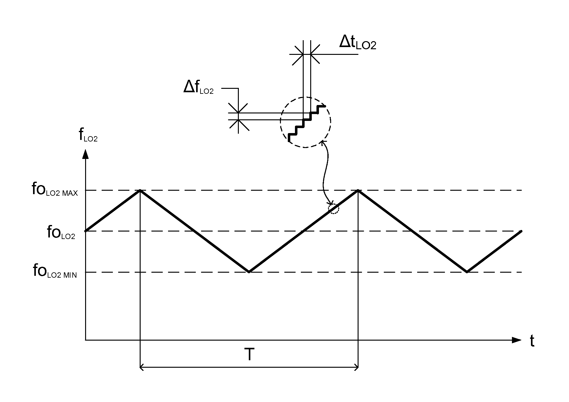
[0033] the value of successive steps is the same over time (the amplitude of the steps is constant).

[0034]According to an embodiment variant, the step can take several successive values over the time.

[0035]The frequency of a local oscillator being most commonly programmed via writing in a register, a “continual” variation consequently corresponds to a series of discrete values. “Continual variation” is defined in contrast to a local oscillator frequency that conserves an identical value for a period of time sufficiently long for an interference phenomenon to arise. In other words, a “continual variation” of a frequency, thus expressed and as described in the context of the present invention, corresponds to a periodic variation for which the period is sufficiently short so that an interference phenomenon can not arise.

[0036]It should also be noted that the definition of a frequency equal to the sum of a fixed frequency and a variable frequency enables the variations relating to one l...

second embodiment

[0077]According to the invention, the frequency excursion of the local oscillator can be around a frequency corresponding to the central frequency foLO2 to which is added a fixed value and not around the central frequency foLO2. If the offset in fixed value is greater than the excursion in one direction (the maximum value of k×Isb), punctual concordance of frequencies of the local oscillator LO1 and LO2 is avoided. The excursion being necessary when foLO1 and foLO2 are equal values. This addition of a fixed offset in addition to the variable offset can only be considered if the maximum excursion on the margin of the central frequency foLO2 of the oscillator LO2 remains within the capacity limits of the demodulator associated with the second tuner 102 following the drift in frequency of the local oscillator LO2.

[0078]According to variants, the wave form of the variation of the frequency fLO2 is sinusoidal, in the form of semi-circles, or a form compatible with the conditions so that ...

third embodiment

[0080]Advantageously, according to the invention, the control unit transmits to the demodulator 104 associated with the tuner 102, a parameter indicating the offset existing between the frequencies foLO2 (central frequency of the local oscillator LO2) and fLO2 (programmed frequency of the local oscillator LO2). The demodulation can be facilitated and be more precise or more reliable.

[0081]The demodulator 104 comprises a calculation module of the offset between the frequency of the channel on which the tuner 102 is tuned and the frequency of the signal received at the input to the demodulator. The demodulator calculates this offset using the value of the frequency of the channel on which the tuner is tuned, this frequency itself is transmitted by the control unit 105 at each reconfiguration (such as for example a change of reception channel on the tuner 102 of the device 1).

[0082]According to a variant, the demodulator 104 comprises an offset value register. Advantageously, the contr...


PUM


Abstract

The invention relates to a Multi-tuner reception system comprising at least a first tuner and a second tuner, the first tuner being adapted to translate a frequency of a first received signal into a first translated frequency, the first tuner comprising a first local oscillator operating at a first local oscillator frequency, the second tuner being adapted to translate a frequency of a second received signal into a second translated frequency, the second tuner comprising a second local oscillator operating at a second local oscillator frequency, wherein the second local oscillator frequency is equal to the sum of the first local oscillator frequency and a continually time variable offset frequency.

Description

1. DOMAIN OF THE INVENTION [0001]The invention relates to the domain of data receiver devices comprising several tuners and more specifically to the reduction of crosstalk between the tuners.2. PRIOR ART[0002]Multi-tuner receivers are used particularly for the reception of several audiovisual programmes via, for example, terrestrial and satellite transmission channels.[0003]Each of the tuners enables selection of a signal carrier frequency within a frequency band in order to demodulate the signal and process it.[0004]Whatever the input architecture of a multi-tuner receiver there is a significant disadvantage. Electromagnetic emissions exist between the tuners and can create interferences. This phenomenon is known as crosstalk.[0005]The problem of crosstalk occurs more specifically when two tuners are tuned onto the same conversion frequency, called LO (Local Oscillator). The demodulators connected respectively to each of the tuner outputs then experience noticeable reductions in pe...

Claims


Application Information

Patent Timeline
IPC IPC(8): H04J1/12
CPCH04J1/12H04B1/109
InventorLOUCHKOFF, MARCFOUQUE, CLAUDEPESIN, ANTHONY
OwnerINTERDIGITAL CE PATENT HLDG