Electromagnetic power transmission for a rotary-wing aircraft or a fixed-wing aircraft

a technology of electromagnetic power transmission and rotary-wing aircraft, which is applied in the direction of positive displacement liquid engine, piston pump, etc., can solve the problems of aircraft and its crew being lost, requiring a relatively large physical size, and not offering optimal safety, so as to suppress the infrared signature of the aircraft

Active Publication Date: 2014-09-04
CHANTRIAUX ERIC +1
View PDF2 Cites 45 Cited by
  • Summary
  • Abstract
  • Description
  • Claims
  • Application Information

AI Technical Summary

Benefits of technology

[0017]Given this situation, an aspect of this invention is to increase the reliability of the transmission assembly, while reducing its physical size, weight and maintenance costs.DISCLOSURE OF THE INVENTION
[0027]Given that the distributed electric motor unit is in direct connection with the rotating shaft, the transmission mechanisms used until now are completely eliminated, and in particular any form of angular gear unit or gearing between the motor element and the rotating shaft or the airscrew, thereby reducing the physical size in relation to the motor units that are familiar from the prior art and increasing considerably the reliability of the transmission chain. Furthermore, the stacked architecture of the electric motor elements makes it possible, in the event of damage being caused to one of the said elements, to continue to transmit sufficient power to the rotating shaft in complete safety by reassigning the power supplied by the undamaged electric motor elements. Similarly, the judicious dimensioning of the electric motor elements avoids all over-dimensioning and permits the achievement of an optimal power-to-weight ratio. The ability to withstand ballistic impacts is fundamental in the field of operations, and the invention offers this improvement.
[0050]The aircraft may also comprise an electronic control unit configured to control the supply of the distributed electric motor unit, the said control unit comprising a program containing instructions for supplying the said electric motor unit uniquely with the electrical energy stored in the storage means and, where appropriate, instructions for simultaneously stopping the function of the generation unit. This is particularly advantageous in order to suppress any infrared signature of the aircraft.

Problems solved by technology

In summary, the aircraft and its crew may be lost in the event of the failure of the mechanical reduction gear.
The output shaft from each engine is offset from the airscrew shaft, however, and a complex system of pulleys and clutches ensures the transfer of energy.
Not only does this system of propulsion necessitate a relatively large physical size, because the engine assembly is over-dimensioned for the envisaged redundancy, but it also does not offer optimal safety in the event of the failure of the pulleys and the clutches.
Here again, this propulsion system does not offer optimal safety in the event of the failure of one of the motors.
The safety of the aircraft would no longer be adequately assured in the event of the failure of the electric motor.
The safety of the aircraft would no longer be assured, however, in the event of the failure of the transmission mechanism.
The safety of the aircraft would no longer be assured in the event of the failure of this transmission mechanism.

Method used


Image

  • Electromagnetic power transmission for a rotary-wing aircraft or a fixed-wing aircraft
  • Electromagnetic power transmission for a rotary-wing aircraft or a fixed-wing aircraft
  • Electromagnetic power transmission for a rotary-wing aircraft or a fixed-wing aircraft

Examples


Embodiment Construction

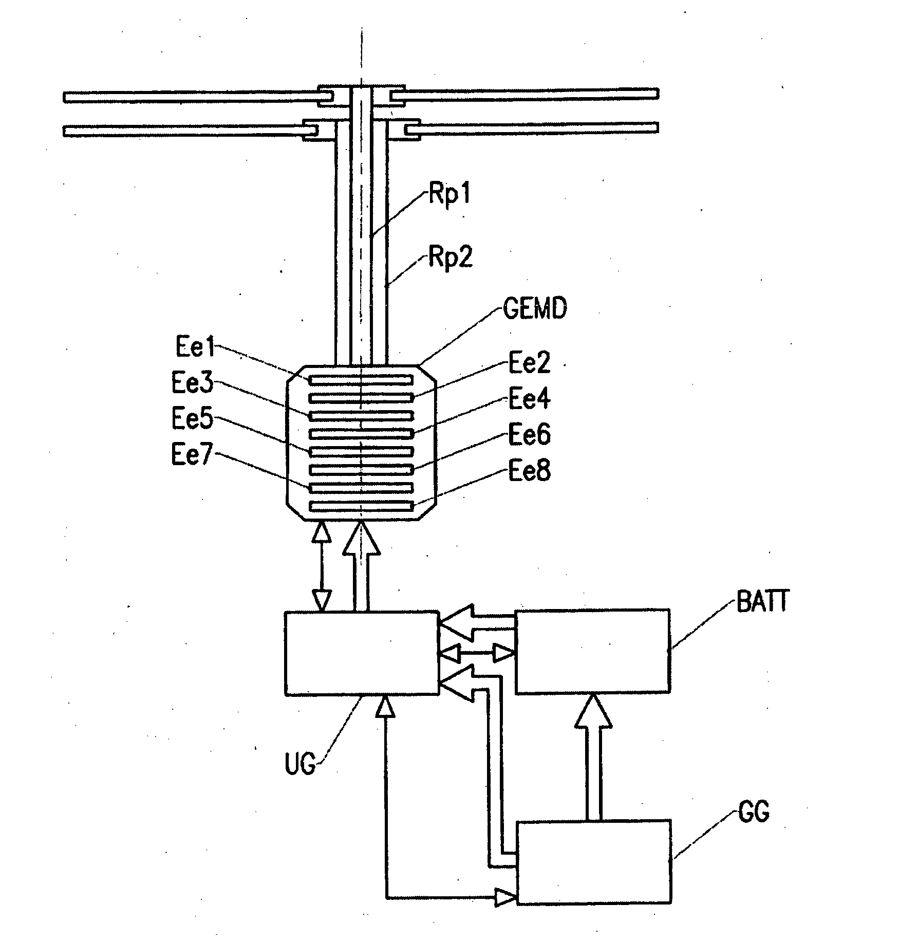
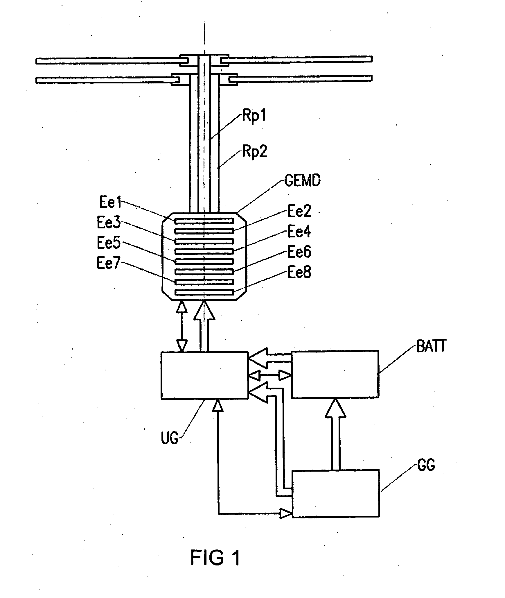
[0060]The propulsion device according to the invention is applicable primarily to redundant distributed electric propulsion, when applied to aircraft having rotary wings (helicopters) or fixed wings (aeroplanes), regardless of whether they are piloted or not (drones), consisting of one or a plurality of airscrews and / or one or a plurality of rotors that are caused to rotate by at least one shaft.

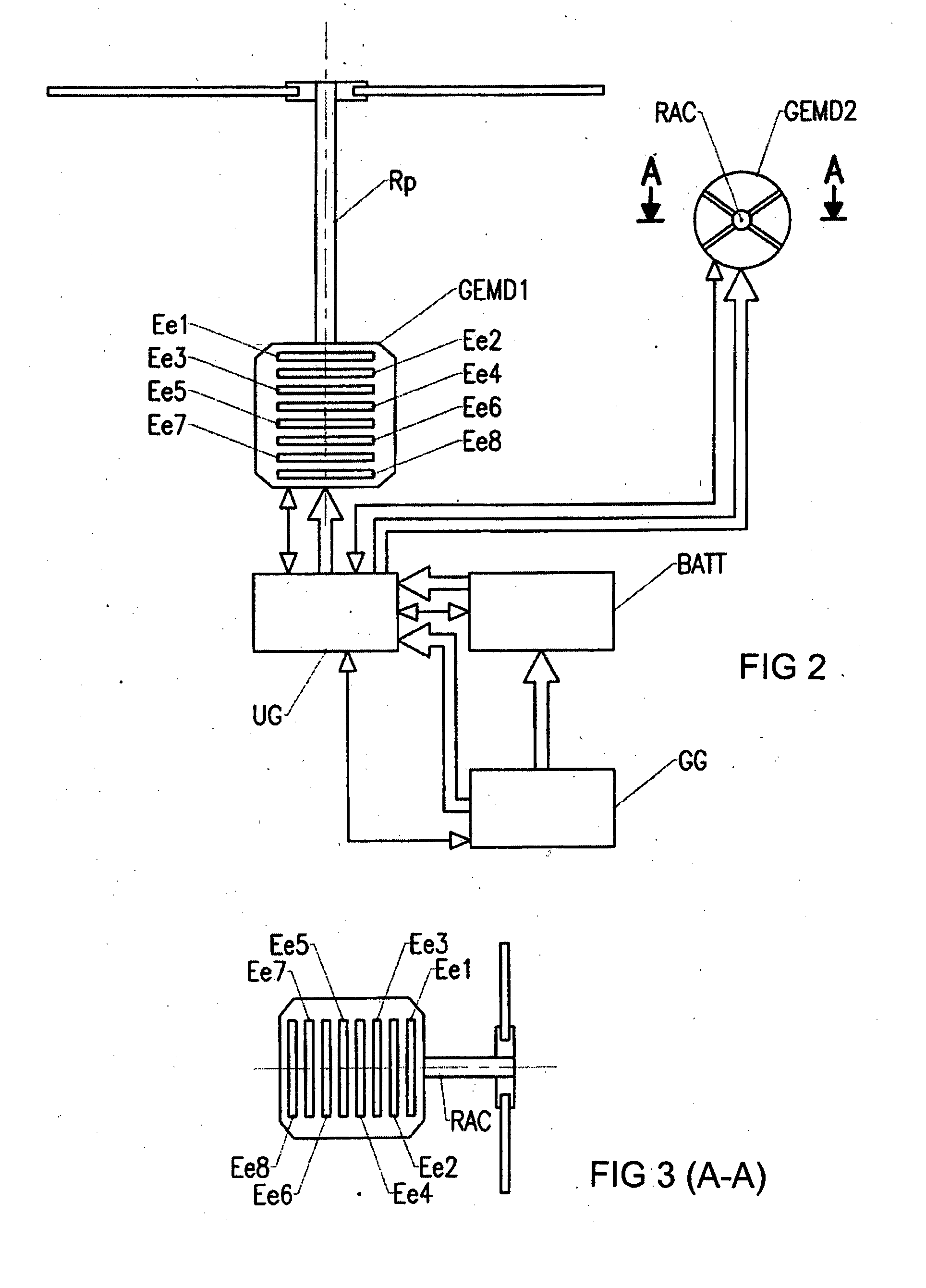
[0061]According to the invention, a motor unit GEMD causes at least one rotor shaft to rotate at a variable or constant speed. In the example shown in FIG. 1, the motor unit GEMD causes two coaxial rotors Rp1, Rp2 of a helicopter to rotate. In the example shown in FIGS. 2 and 3, a motor unit GEMD1 causes the main rotor Rp of a helicopter to rotate, and another motor unit GEMD2 causes the anti-torque tail rotor (RAC) to rotate. In the example shown in FIG. 4, the motor unit GEMD causes the shafts on which coaxial airscrews H are mounted to rotate.

[0062]According to the invention, the motor un...


PUM


Abstract

Rotary-wing aircraft or fixed-wing aircraft consisting of one or a plurality of rotors and / or one or a plurality of airscrews being caused to rotate by means of at least one shaft, the said aircraft comprising a distributed electric motor unit configured to ensure the propulsion and / or the lifting of the said aircraft by causing the said shaft to rotate, the motor unit being a distributed electric motor unit connected directly to the rotating shaft, no mechanism for the transmission of movement being interposed between the said CND unit and the said shaft, the distributed electric motor unit being composed of a plurality of stacked electric motor elements, each said electric motor element being connected directly to the rotating shaft and consisting of at least one fixed stator and at least one moving rotor capable of connection to the said rotating shaft in order to transmit to it a mechanical power of the following kind where: Pr=the nominal mechanical power necessary for the propulsion and / or for the lifting of the said aircraft, Pim=the maximum mechanical power capable of being delivered by the electric motor element on level i, to the rotating shaft, for instance Pim<Pr, Ki=the power derating of the electric motor element on level i, for instance 0≦ki≦1, Ki being a variable that is adjustable as a function of the undamaged number of electric motor elements and / or as a function of the nominal mechanical power necessary for the propulsion and / or for the lifting of the said aircraft at a moment in time t, n=the number of electric motor elements comprising the distributed electric, motor unit, for instance n≧2,—the axes of rotation of the moving rotors and of the rotating shaft being coaxial.

Description

[0001]This application claims priority from French Application No. 1157828 filed on 4 Sep. 2011, the contents of which are to be taken as incorporated herein by this reference.DESCRIPTION[0002]1. Technical Field of the Invention[0003]The present invention is directed to a rotary-wing aircraft or a fixed-wing aircraft equipped with a distributed electric motor unit composed of a stack of electric motor elements, each producing a fraction of the total power necessary for the setting in rotation of a rotor shaft.[0004]The invention relates to the technical field of electromagnetic power transmissions applied to aircraft having fixed wings (aeroplanes) or rotary wings (helicopters), regardless of whether these are piloted or not (for example: drones).[0005]2. State of the Art[0006]Traditional propulsion systems for aircraft generally consist of a thermal engine or turbo shaft engines or turbo-fan engines and a mechanical reduction gear coupled to the rotor shaft. The reduction gears are...

Claims


Application Information

Patent Timeline
Patent Type & Authority Applications(United States)
IPC IPC(8): F04D13/06
CPCF04D13/06B64C27/14B64D27/24B64D35/02B64D35/08B64D2221/00Y02T50/40B64U50/19Y02T50/60
Inventor CHANTRIAUX, ERICCHRETIEN, PASCAL
Owner CHANTRIAUX ERIC
Why Eureka
Try Eureka