In-air ultrasonic rangefinding and angle estimation

an ultrasonic rangefinding and angle estimation technology, applied in the field of sensor systems, can solve the problems of large size of optical 3d imagers for gesture recognition, high power consumption, and general inability to operate in sunlight, and achieve the effect of less power

Active Publication Date: 2014-09-11
RGT UNIV OF CALIFORNIA
View PDF6 Cites 30 Cited by
  • Summary
  • Abstract
  • Description
  • Claims
  • Application Information

AI Technical Summary

Benefits of technology

[0012]By way of example, and not of limitation, the present invention uses ultrasound waves to measure the range and angle to targets. In one embodiment, an ultrasound wave is emitted from one or more ultrasound transceivers, and one or more ultrasound transceivers are used to detect the echo. Time diversity in the transmitted signal allows the time-of-flight to be calculated which is used to infer the range to the target. A spatial array of transceivers allows the direction of the returning wave to be calculated.
[0013]The use of sound to measure the depth of the surroundings is attractive because the speed of sound is roughly one million times slower than the speed of light. Therefore, for similar wavelength, resolution, and accuracy, a system can operate at a frequency ˜1 million times lower than that of an optical / RF system. This allows the use of low-speed, power efficient electronics that enables the system to consume orders of magnitude less power.

Problems solved by technology

However, there are many situations where a touch screen is inappropriate or could be complemented by an interface that does not require the user to touch the screen.
Optical 3D imagers for gesture recognition suffer from large size and high power consumption.
Their performance depends on ambient illumination and they generally cannot operate in sunlight.
For example, the Microsoft Kinect 3D imaging system consumes 12 watts, has a volume of over 675 cm3, and cannot operate in sunlight.
These factors prohibit use in portable electronics.
However, use of continuous wave signals is susceptible to multipath interference, and requires extremely high dynamic range in the receive electronics.
Multipath interference arises when transmitted waves reflect off several targets and arrive back at the receiver.
If the waves have a slightly different path length, they can combine destructively, thereby canceling the return signal.
This requires large dynamic range.

Method used


Image

  • In-air ultrasonic rangefinding and angle estimation
  • In-air ultrasonic rangefinding and angle estimation
  • In-air ultrasonic rangefinding and angle estimation

Examples


Embodiment Construction

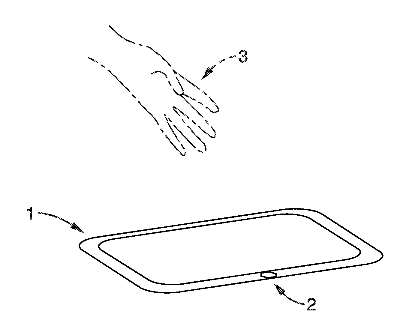
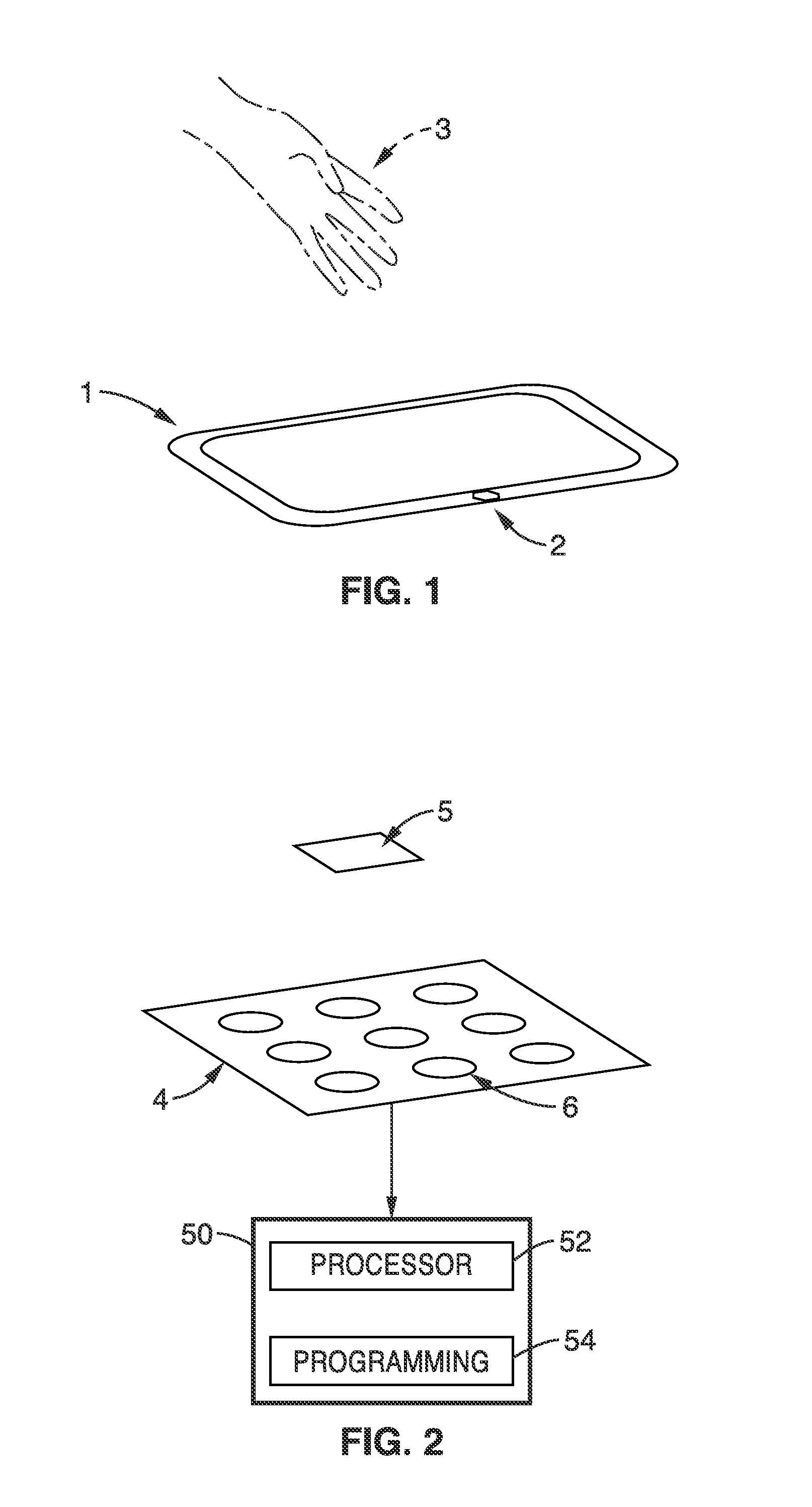
[0034]The present invention generally comprises an ultrasonic depth sensor which can be used to measure the position and configuration of a user's hand(s) with respect to an electronic device (hereafter “computer”) in order for the user to generate input into the computer. The sensor may be configured to detect motions of the user's entire hand or individual fingers. The computer translates the user's motions into input commands for the computer, and may generate visual, audio, or tactile feedback to the user.

[0035]The system of the present invention differs from prior approaches in several ways. For example, the system of the present invention also uses pulse-echo excitation and closely spaced arrays of transducers, where the phase and amplitude of the transducers can be controlled to provide angular resolution.

[0036]FIG. 1 shows an embodiment of a sensor system according to the present invention. Computer 1 has a depth sensor 2 mounted on it such that sound waves are emitted towar...


PUM


Abstract

An apparatus for determining location of a moveable object in relation to an input device includes an array of one or more piezoelectric micromachined ultrasonic transducer (pMUT) elements and a processor. The array is formed from a common substrate. The one or more pMUT elements include one or more transmitters and one or more receivers. The processor configured to determine a location of a moveable object in relation to an input device using sound waves that are emitted from the one or more transmitters, reflected from the moveable object, and received by the one or more receivers.

Description

CROSS-REFERENCE TO RELATED APPLICATIONS[0001]This application claims the benefit of U.S. provisional patent application Ser. No. 61 / 776,403 filed on Mar. 11, 2013, incorporated herein by reference in its entirety.STATEMENT REGARDING FEDERALLY SPONSORED[0002]Not ApplicableINCORPORATION-BY-REFERENCE OF COMPUTER PROGRAM APPENDIX[0003]Not ApplicableBACKGROUND OF THE INVENTION[0004]1. Field of the Invention[0005]The present invention pertains generally to a sensor system, and more particularly to a system which can measure the range and direction to objects that are located in front of the sensor system.[0006]2. Description of Related Art[0007]Alternatives to the keyboard and mouse are being rapidly deployed in computers, smartphones, and tablets. The touch screen interface has gained traction in all three markets and dominates the smartphone and tablet market. The touch screen allows intuitive interfaces based on software buttons to be used and is especially ideal for small screens wher...

Claims


Application Information

Patent Timeline
Patent Type & Authority Applications(United States)
IPC IPC(8): G06F3/01
CPCG06F3/017G06F3/043G06F2203/04101
Inventor BOSER, BERNHARD E.PRZYBYLA, RICHARD J.GUEDES, ANDREHORSLEY, DAVID A.SHELTON, STEFON E.
Owner RGT UNIV OF CALIFORNIA
Why Eureka
Try Eureka