X-Ray Backscatter Imaging of an Object Embedded in a Highly Scattering Medium

a highly scattering medium and backscatter imaging technology, applied in the field of backscatter imaging techniques, can solve the problems of not easily admitting repeatable investigations, providing no information about the composition of objects, and high cost of instances, and achieves the effect of high energy and sufficient strength

Active Publication Date: 2014-09-11
VISURAY INTECH LTD
View PDF6 Cites 5 Cited by
  • Summary
  • Abstract
  • Description
  • Claims
  • Application Information

AI Technical Summary

Benefits of technology

[0013]A system for imaging an object disposed in a scattering medium using backscatter obtained from a source of electromagnetic radiation is provided, the system including at least: an electromagnetic radiation source of sufficiently high energy as to penetrate through a medium in which an object is disposed, the source emitting electromagnetic radiation of sufficient strength to form an image of the object; a means for restricting electromagnetic radiation emitted from the source; one or more detectors that detect energy emitted within a predetermined energy range and create electronic data associated therewith; and a software control system disposed in communication with a processor, wherein said software control system further comprises means for assembling and translating detected data into an electronic image representative of the shape of the object.
[0014]An associated method for imaging an object disposed in a scattering medium using backscatter from a source of electromagnetic radiation is also provided, the method including at least: emitting electromagnetic radiation from an electromagnetic radiation source, wherein the radiation is emitted at a sufficient strength as to penetrate through a medium in which an object is disposed and thereafter form an image of the object; restricting electromagnetic radiation emitted from the source; detecting energy emitted within a predetermined energy range; creating electronic data associated with said detected energy; disposing a software control system in communication with a processor, and using said software control system to assemble detected data into an electronic image representative of the shape of the object.

Problems solved by technology

Obtaining accurate data describing the shape and composition of objects located in a borehole has traditionally been a challenge, primarily due to the high temperatures and pressures within the borehole, the presence of associated opaque liquids, and significant space and maneuvering constraints.
Furthermore, well operators need to obtain information as quickly as possible in order to minimize delays in operation, which can in some instances be extremely expensive.
However, since the impression must be brought to the surface for subsequent examination, this technique is time-consuming and does not easily admit to repeatable investigations.
This approach provides no information about the composition of the object, however.
Unfortunately, this method can only be used to look radially at the borehole walls or casing, and cannot be used to visualize objects disposed axially within the borehole.
While acoustic methods can provide quick feedback, they all have the drawbacks that any resulting data requires prior knowledge of the shape of the object; generally do not produce sufficiently clear images; and the results ultimately require expert interpretation.
As a general matter, any technique using light at various optical wavelengths will suffer from distortion caused by the opacity of well fluids at those wavelengths.
In order to obtain a clear image, the well fluids must therefore be replaced, which is a very costly and time-consuming operation.
Unfortunately, millimeter wavelength imaging cannot provide information about the composition of the object.
In all of these systems, however, the radiation is directed radially, and none are capable of visualizing an object located axially along the well.
The x-ray imaging technique disclosed therein can produce images of objects located axially in the well, but affords very limited view depth and insufficient image clarity due to scattering by the well fluids.
While high energy radiation can penetrate through the optically opaque fluid to scatter from the target object, the radiation still scatters within the fluid and some of this scattering inevitably enters the detector.
Consequently, objects become obscured as the distance between the x-ray source and object increases, thereby limiting the range of applicability of the methods.

Method used


Image

  • X-Ray Backscatter Imaging of an Object Embedded in a Highly Scattering Medium
  • X-Ray Backscatter Imaging of an Object Embedded in a Highly Scattering Medium
  • X-Ray Backscatter Imaging of an Object Embedded in a Highly Scattering Medium

Examples


Embodiment Construction

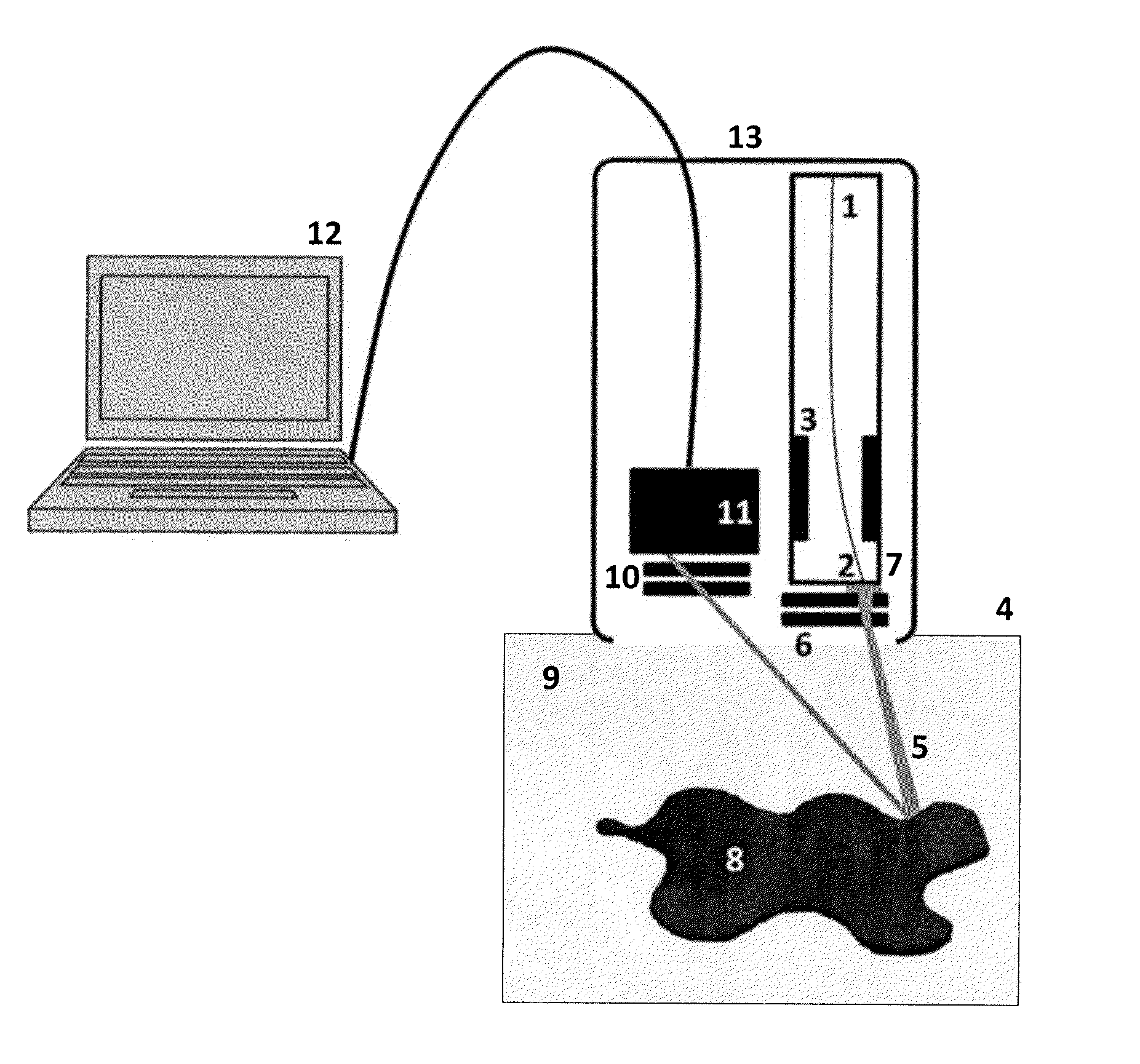
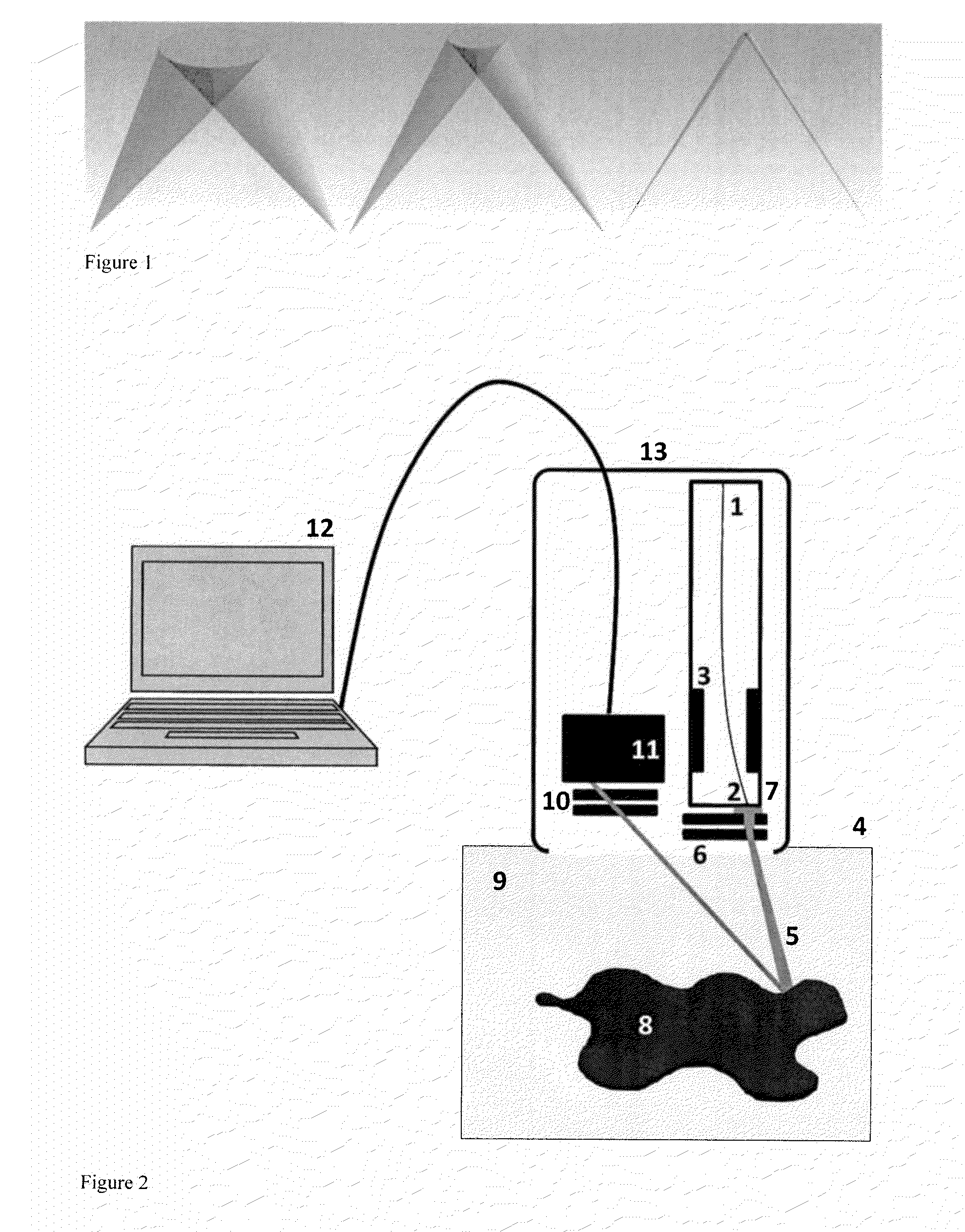
[0019]The invention described here comprises an apparatus and method for obtaining a three-dimensional representation of a target object within a fluid-carrying conduit, such as a hydrocarbon exploration or production well, using high energy photons. The representation is essentially a three-dimensional image that achieves visualization of the shape of the target object despite the intervening opaque fluids located between the imaging tool and the object.

[0020]According to one example embodiment, a narrow, pencil-shaped beam of radiation is scanned in coordination with a similarly narrow detector field-of-view in order to sample the radiation scattering properties of only a small volume of material at any given time. The result is a clearer visualization with a greater viewing depth.

[0021]In order to create the clear visualization required, the scattering from the fluid that reaches the detectors must be minimized. This is achieved by forming the source radiation into a narrow beam,...


PUM

PropertyMeasurementUnit
thickaaaaaaaaaa
distanceaaaaaaaaaa
distanceaaaaaaaaaa

Abstract

An apparatus and associated method for obtaining a three-dimensional representation of a target object within a fluid-carrying conduit, such as a hydrocarbon exploration or production well, using high energy photons is provided. The representation is essentially a three-dimensional image that achieves visualization of the shape of the target object despite the intervening opaque fluids located between the imaging tool and the object. In one specific though non-limiting embodiment, a narrow, pencil-shaped beam of radiation is scanned in coordination with a similarly narrow detector field-of-view in order to sample the radiation-scattering properties of only a small volume of material at any given time. The result is a clearer to visualization with a greater viewing depth.

Description

FIELD OF THE INVENTION[0001]The present invention relates generally to backscatter imaging techniques, and in a particular though non-limiting embodiment to an apparatus and method for obtaining a three-dimensional representation of a target object within a fluid-carrying conduit, such as a hydrocarbon exploration or production well, using high energy photons.BACKGROUND OF THE INVENTION[0002]Obtaining accurate data describing the shape and composition of objects located in a borehole has traditionally been a challenge, primarily due to the high temperatures and pressures within the borehole, the presence of associated opaque liquids, and significant space and maneuvering constraints. Furthermore, well operators need to obtain information as quickly as possible in order to minimize delays in operation, which can in some instances be extremely expensive. Known techniques for obtaining such images can be categorized in three basic classes: (1) those that use deformation of a mechanical...

Claims


Application Information

Patent Timeline
Patent Type & Authority Applications(United States)
IPC IPC(8): G01N23/203
CPCG01N23/203E21B47/092
Inventor SAFINYA, KAMBIZVOLL, ADNESOFIIENKO, ANDRIIPONCE, DAVIDSPANNUTH, MELISSATORSTEINSEN, HENNING
Owner VISURAY INTECH LTD
Why Eureka
Try Eureka