Locomotive natural gas storage and transfer system

a technology of natural gas storage and transfer system, which is applied in the direction of locomotives, transportation and packaging, machines/engines, etc., can solve the problems of increased weight and complexity, limited existing system of locomotives, and additional rail cars to the train, etc., to maximize the opportunities of natural gas fueled vehicles, increase density, and prolong storage time in the tank

Active Publication Date: 2014-09-18
RAIL GAS TECH
View PDF2 Cites 16 Cited by
  • Summary
  • Abstract
  • Description
  • Claims
  • Application Information

AI Technical Summary

Benefits of technology

[0012]The proposed invention is an integrated on vehicle natural gas storage and transfer system (CNG or LNG) that maximizes storage capacity, minimizes space claim and structure weight, and incorporates specific features to meet or exceed the industry performance, safety and functional requirements for general rail use. The system is modular and adaptable for under frame or tender car storage applications consisting of mounting frames or enclosures and tank modules that are contained within them. The frames and enclosures are specifically designed for tender car or underframe mounting and can support commercially available cylinders and tanks or specially developed tank modules. The tank modules are removable, serviceable units fitted with optimized cylinders or tanks allowing ideal integration solutions for CNG or LNG storage.

Problems solved by technology

The storage tanks and support equipment used in existing systems are repurposed from other industries in commercially available sizes and configurations that are less than ideal for high horsepower, mobile applications.
As a result, existing systems for locomotives, both CNG and LNG have been limited to specific local application and pilot or research projects that do not necessarily require large storage capacity, ease of service, maintainability or adherence to regulations such as crash worthiness necessary for general use on freight and passenger lines.
In off road mobile applications, the most significant technical challenge is attaining the necessary DGE capacity to motivate manufacturers and end users to convert from diesel fuel.
For tenders and flat cars, it is possible to attain acceptable storage capacity, but results in additional rail cars to the train consist and / or added weight and complexity for the operators to deal with.
For underframe storage, these existing components and packaging schemes limit the storage density, thus limiting the range, performance and functionality of the vehicle the system is supporting.
Underframe or belly mounted tanks in place of or in addition to the existing fuel tanks on the locomotive present greater challenges in package and storage capacity as well as introducing additional requirements for crash worthiness criteria and other safety regulations.
This approach makes mounting and servicing the tanks less than ideal as it requires removing the enclosure with all the tanks at once as one assembly.
Another downside of this type of longitudinal tank arrangement is its lack of storage density when the longitudinal space to put the tanks in is less than 9 feet as it is with typical switcher locomotives.
This results in a higher quantity of shorter tanks, reducing the storage capacity and increasing the cost as well as the number of components and potential leak points.
For both tender car and underframe NG storage, maximizing capacity requires close spacing of the NG cylinders making mounting the tanks in tender cars or under frame enclosures a challenge.
The switcher has metal on metal wheels and will see significantly more vertical vibration, this will affect the loose fit in the sliding pin block causing degradation of the pin material where it meets the block, as the locomotive CNG tank is longer and heavier it could also cause fatigue in the aluminum neck boss material and a tank failure at the tank neck.
The most significant detriment to the neck mounting system is the operation of the switcher locomotive, its primary purpose is to frequently couple and uncouple with rail cars, and these coupling events lead to repeated impulse loads of several g's.
These repeated impulses could be a fatigue risk to conventional neck mounted composite CNG cylinders if the loads are significant and perpendicular to the axis of the tank.
The issue with strap mounting of CNG cylinders is that access is needed to tighten the straps from the side and this will require spacing the tanks further apart thus reducing the total number of CNG cylinders and total fuel capacity.
This becomes a problem when an agency has several hundred busses with some of them idle.
Also as LNG is stored for a long period of time and is venting, its percentage of methane will drop over time as methane boils off first.
Using fuel that has weathered too long can result in engine damage.
Further this system requires heat to be added to the tank to raise the pressure or off gassing or flaring of vaporized natural gas if it is not consumed in time by the engine, both of which expend energy or release fuel which further reduced range and efficiency
This is especially a problem when refueling large pieces of offload equipment from LNG tanker trucks.
A further challenge in passive LNG tank systems is maintaining the required tank pressure when the engine is at high loads and consuming a large amount of fuel over an extended time.
When this small amount of fuel boils off, it absorbs a large amount of latent heat and chills the remaining liquid.
This was a particular problem with the LNG switchers at LA Junction RR, the locomotives could only operate at high power for a short time before low LNG tank pressure forced the system to reduce engine power output.

Method used


Image

  • Locomotive natural gas storage and transfer system
  • Locomotive natural gas storage and transfer system
  • Locomotive natural gas storage and transfer system

Examples


Embodiment Construction

[0068]To facilitate an understanding of the present disclosure, a number of terms and phrases are defined below:

[0069]Throughout this document, certain systems have been described for use with CNG, or LNG cylinders or vessels. It should be noted that these concepts would be usable for high pressure or cryogenic vessels containing any pressurized and / or liquefied gaseous fuel including hydrogen.

[0070]ISO Tank Module: Intermodal tank system with an ISO specified frame for stacking with other intermodal containers.

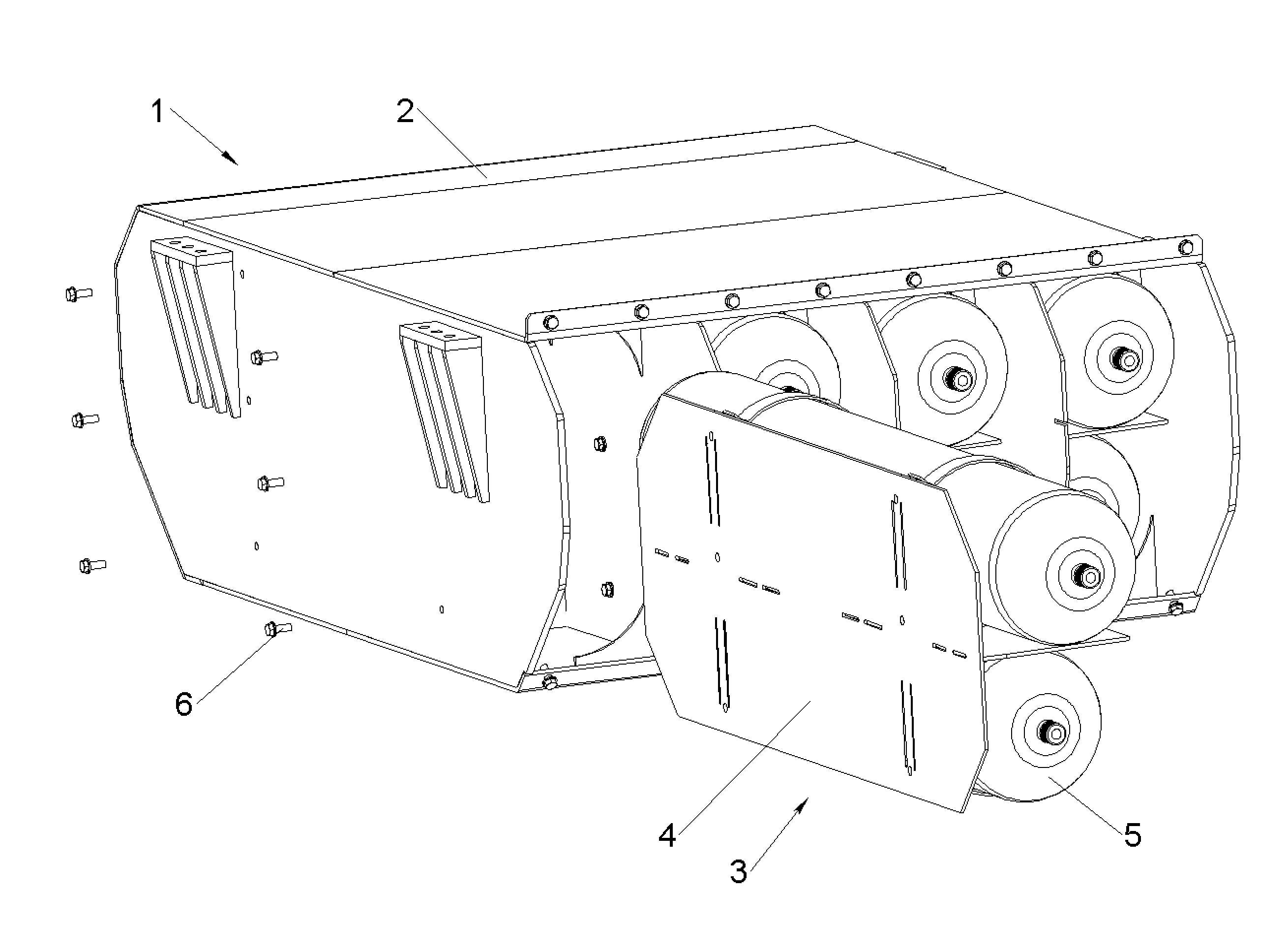
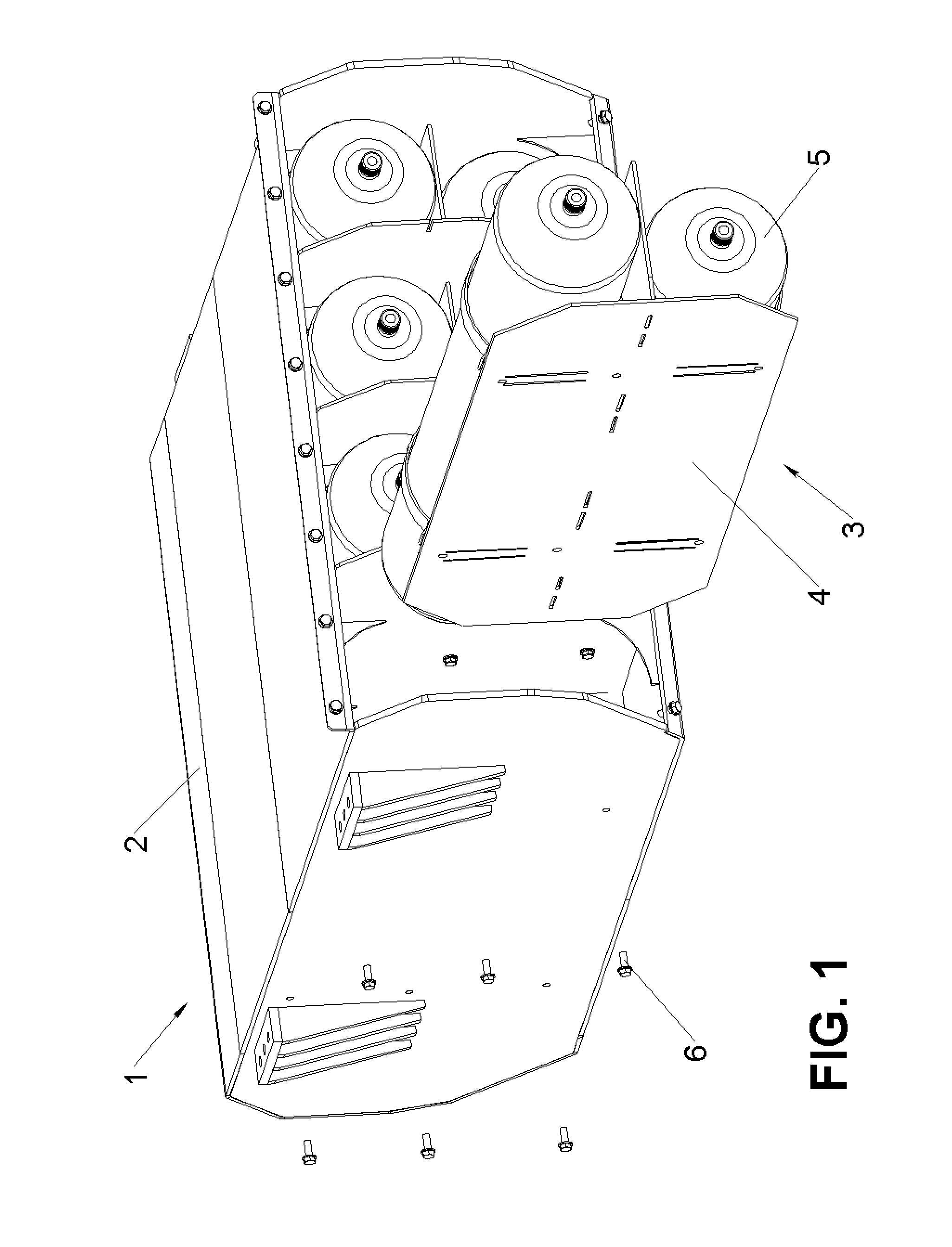
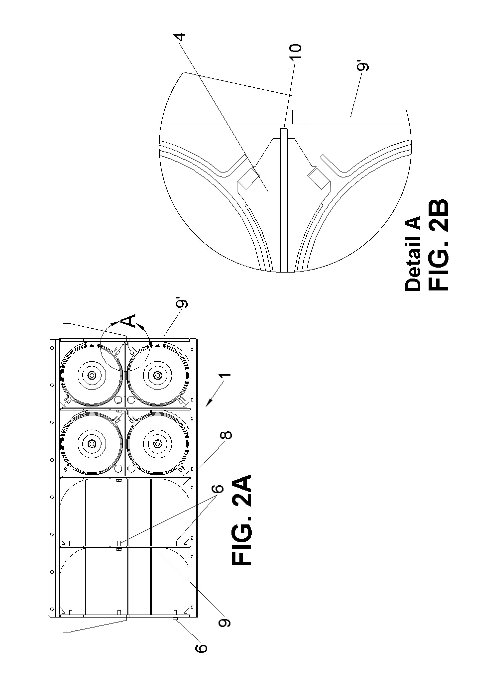
[0071]The first portion of the detailed description relates to a locomotive underframe CNG fuel storage system. FIG. 1 illustrates a CNG storage system 1 that is composed of one Crashworthy Enclosure 2 and at least one CNG cylinder module 3. In this embodiment, CNG storage system 1 incorporates four CNG cylinder modules 3.

[0072]The second portion of the detailed description relates to a crashworthy enclosure. The Crashworthy Enclosure 2 is a semi monocoque structure configure...


PUM


Abstract

A locomotive underframe CNG fuel storage system including: a crashworthy enclosure including a removable side panel and a permanent side panel welded into place; and at least one CNG cylinder module, wherein each CNG cylinder module includes a plurality of CNG cylinders stacked vertically, secured to a vertical wall, and separated by a horizontal plate, wherein the horizontal plate extends towards but does not contact the vertical wall when the vertical wall is planar and, further wherein, the horizontal plate supports the vertical wall from moving further out of plane when vertical axial weight causes the vertical wall for move out of plane towards the horizontal plate.

Description

CROSS-REFERENCE TO RELATED APPLICATIONS[0001]This application claims the benefit of U.S. Provisional Application No. 61 / 790,771 filed on Mar. 15, 2013, the entirety of which is incorporated herein by reference.BACKGROUND OF THE INVENTION[0002]Current state of the art for storage and transfer of natural gas (NG) to engines used in mobile off road applications consist primarily of commonly available components and existing technology configured for demonstration. The storage tanks and support equipment used in existing systems are repurposed from other industries in commercially available sizes and configurations that are less than ideal for high horsepower, mobile applications. For locomotive applications, these systems are made up of dedicated NG tender cars, or standard tanks mounted on flat railcars or fixed underframe between the trucks.[0003]As a result, existing systems for locomotives, both CNG and LNG have been limited to specific local application and pilot or research proje...

Claims


Application Information

Patent Timeline
Patent Type & Authority Applications(United States)
IPC IPC(8): B61C17/02B61D15/06
CPCB61D15/06B61C17/02F01N3/103F01N13/085F01N13/10F01N13/1816F01N2340/02F01N2340/06F01N13/0093F01N3/20F01N3/2066F01N2610/02Y02T10/12Y02T30/00B61C3/02
Inventor COOK, DAVID
Owner RAIL GAS TECH
Why Eureka
Try Eureka