Ignition apparatus

a technology of ignition apparatus and spark plug, which is applied in the direction of mechanical equipment, machines/engines, instruments, etc., can solve the problems of difficult to generate a spark discharge for starting combustion, high pressure in the combustion chamber of the combustion chamber, and increased environmental conservation and fuel depletion

Active Publication Date: 2014-09-18
MITSUBISHI ELECTRIC CORP
View PDF20 Cites 9 Cited by
  • Summary
  • Abstract
  • Description
  • Claims
  • Application Information

AI Technical Summary

Benefits of technology

[0011]This invention has been accomplished in order to solve such problems in the conventional apparatus as described above, and it is an object of the invention to provide an ignition apparatus that can obtain the effect that can cancels out the quenching effect and the like with a low-cost and simple structure.

Problems solved by technology

In recent years, the problems of environmental conservation and fuel depletion have been raised.
It has been known that when an internal combustion engine (hereinafter also referred to as an “engine”) is in a highly supercharged state, the pressure in the combustion chamber thereof becomes very high even in a state that does not accompany combustion, so it becomes difficult to generate a spark discharge for starting combustion.
In reality, however, it is currently difficult to ensure sufficient withstanding voltage for meeting the demand, so the circumstance is that there is no other choice than choosing the means to narrow the gap distance of the spark plug.
Nevertheless, when the gap of the spark plug is narrowed, another problem arises that the quenching effect of the electrode portion tends to bring about undesirable effects, causing degradation in startability and degradation in combustion performance.
However, it has been difficult to adopt such a structure because of the viewpoint of lead-free design in recent years.
Consequently, problems arise that size reduction becomes difficult and the manufacturing cost becomes very high.
However, a device that is capable of high-frequency and high current switching and also ensuring reliability is very costly, so this also causes the problem of very high manufacturing cost.

Method used


Image

  • Ignition apparatus
  • Ignition apparatus
  • Ignition apparatus

Examples


first preferred embodiment

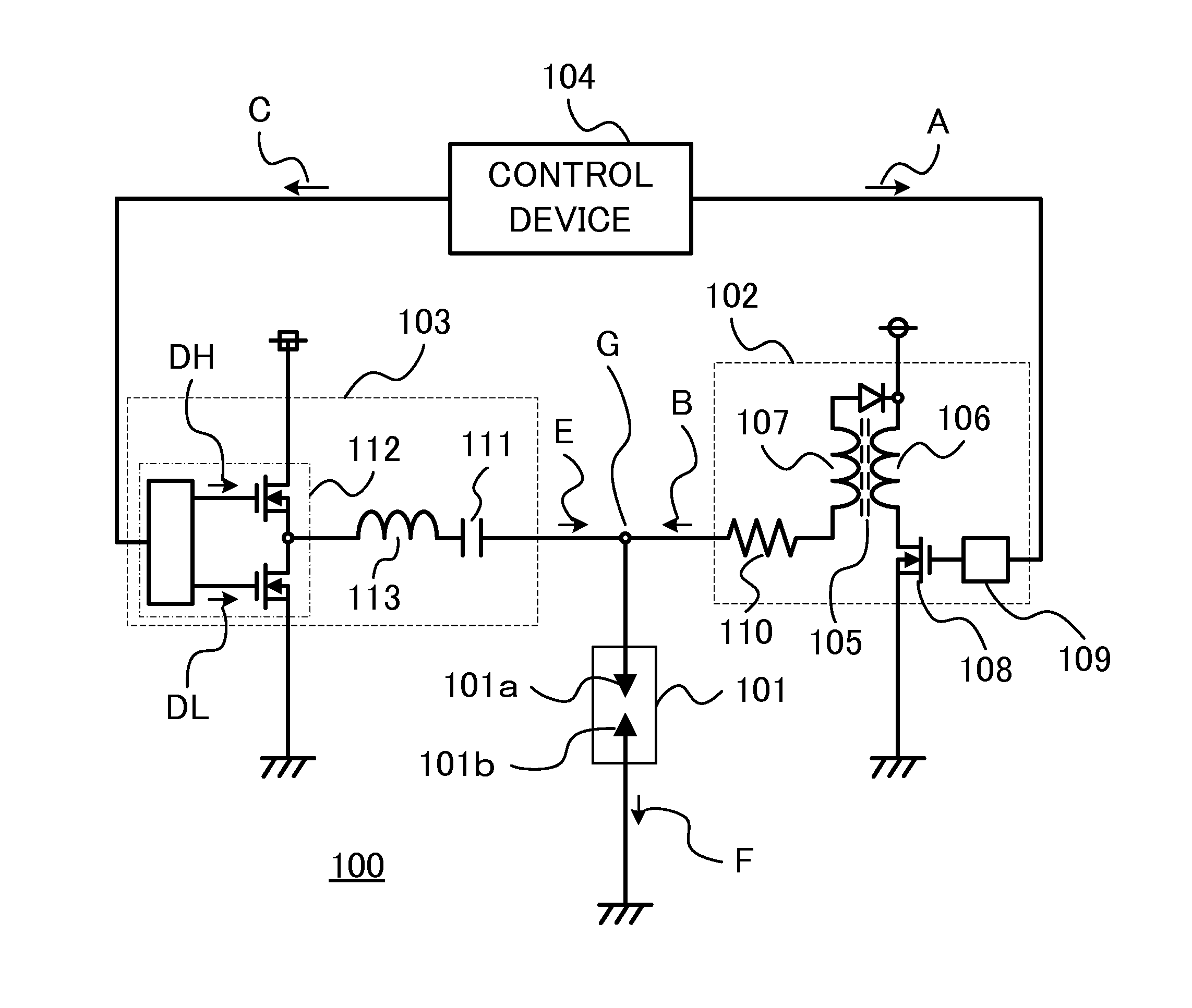
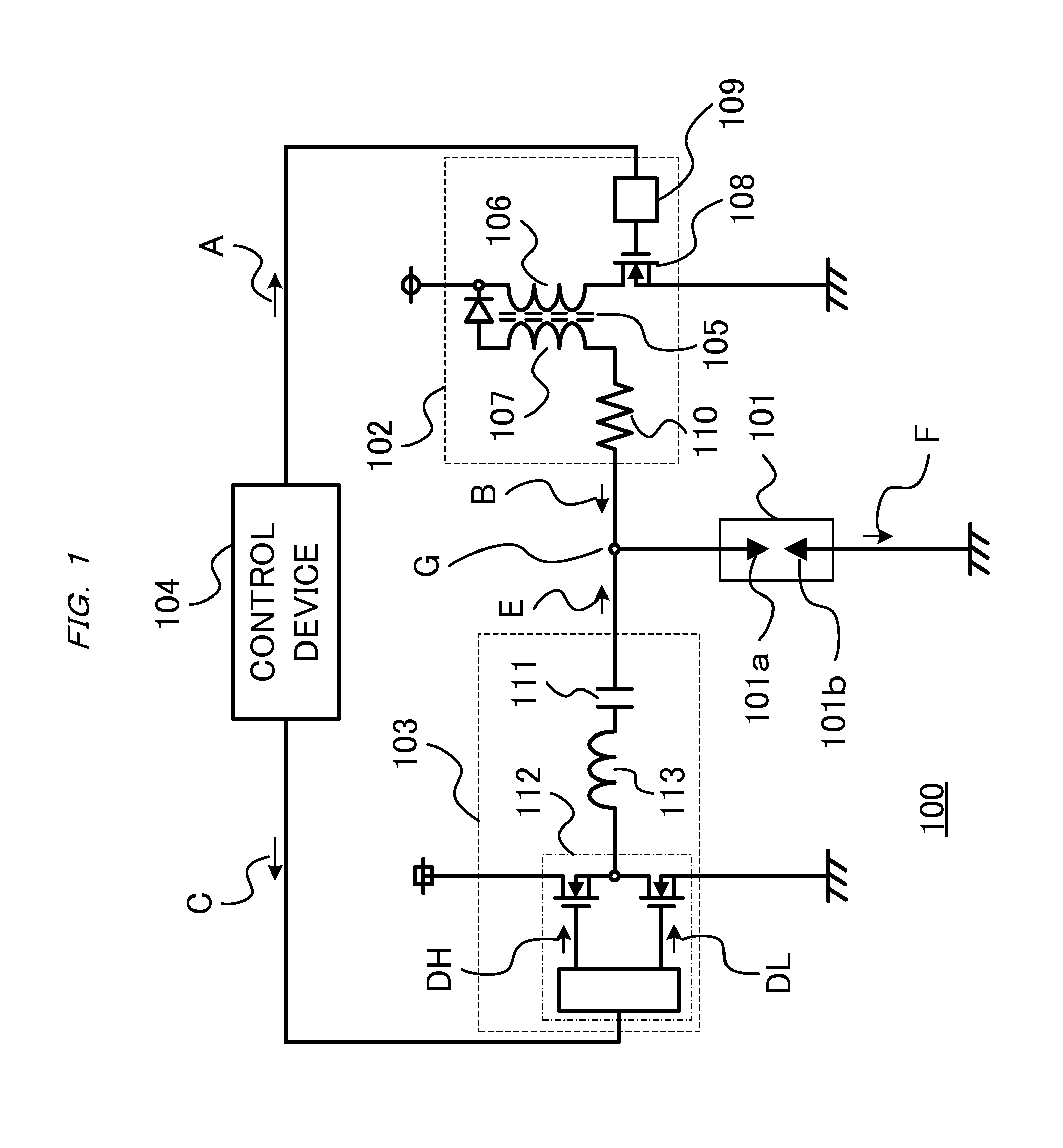
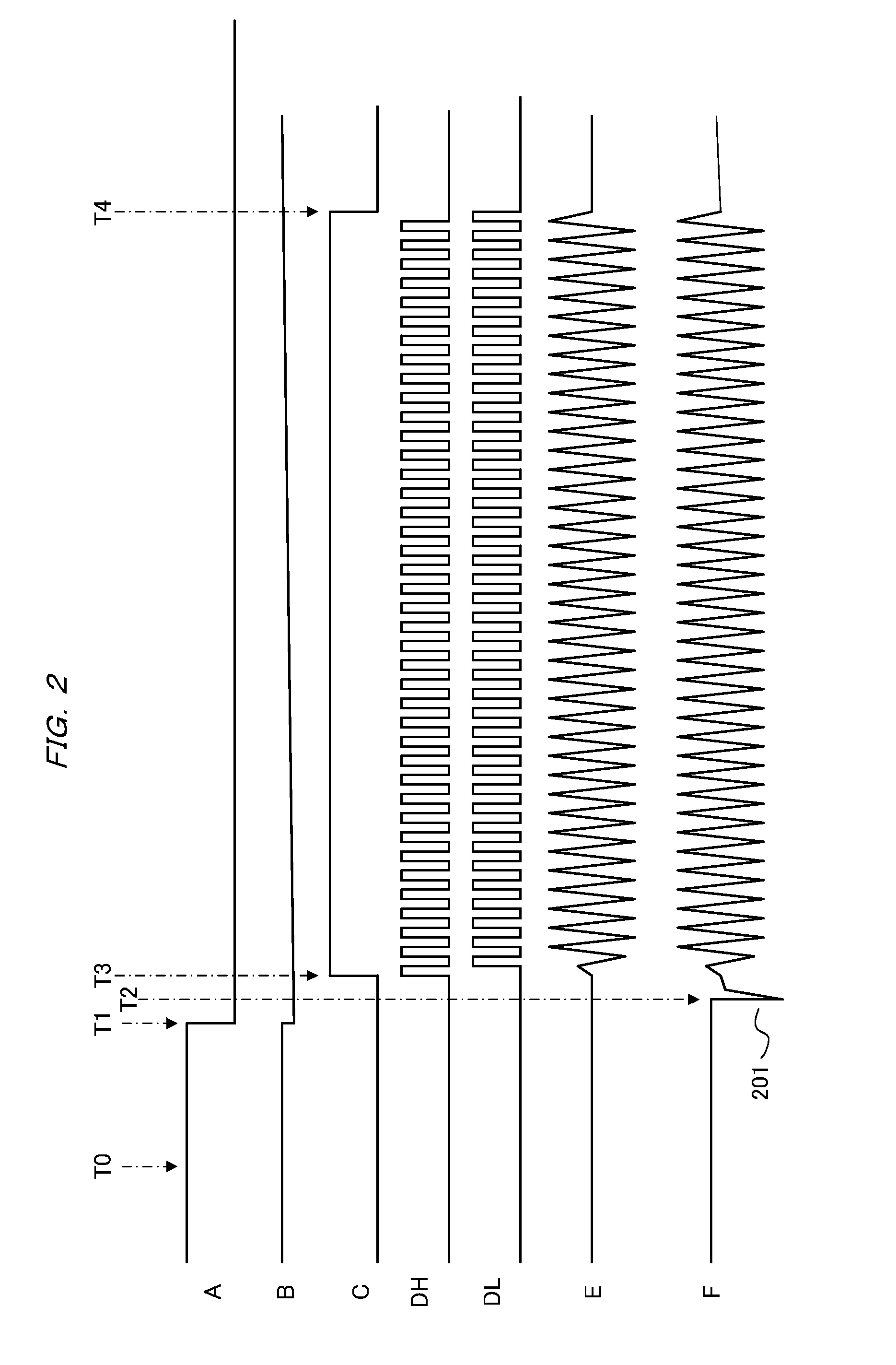
[0018]FIG. 1 is a configuration diagram of an ignition apparatus according to a first preferred embodiment of this invention. Referring to FIG. 1, an ignition apparatus 100 includes a spark plug 101 that generates a spark discharge to ignite a combustible fuel mixture in a combustion chamber in an internal combustion engine, an ignition coil device 102 serving as a spark discharge path generating device that applies a predetermined high voltage to the spark plug 101 to form a spark discharge path, a high frequency power supply 103 serving as a current supplying device that supplies an alternating current to form large discharge plasma in the spark discharge path, and a control device 104 that controls operation timing of the high frequency power supply 103. The control device 104 also controls the operation of the ignition coil device 102.

[0019]The spark plug 101 has a high voltage electrode 101a serving as a first electrode, and an external electrode 101b serving as a second electr...


PUM


Abstract

An ignition apparatus includes a spark plug having a high voltage electrode and an external electrode facing each other across a gap and being configured to generate a spark discharge in the gap to ignite a combustible fuel mixture in a combustion chamber of an internal combustion engine, an ignition coil device configured to generate a predetermined high voltage and supply the high voltage to the high voltage electrode to form a path for the spark discharge in the gap, a high frequency power supply having a band-pass filter and being configured to supply an alternating current to the spark discharge path, and a control device configured to control operation timing of the high frequency power supply. The band-pass filter passes a frequency of from 1 MHz to 4 MHz.

Description

BACKGROUND OF THE INVENTION[0001]1. Field of the Invention[0002]This invention relates to an ignition apparatus used mainly for operations of an internal combustion engine.[0003]2. Description of the Related Art[0004]In recent years, the problems of environmental conservation and fuel depletion have been raised. In the automobile industry, it is an urgent task to deal with these problems. An example of the solution is a method of remarkably improving fuel consumption by engine downsizing utilizing a supercharger or by weight reduction.[0005]It has been known that when an internal combustion engine (hereinafter also referred to as an “engine”) is in a highly supercharged state, the pressure in the combustion chamber thereof becomes very high even in a state that does not accompany combustion, so it becomes difficult to generate a spark discharge for starting combustion. One of the reasons is that the voltage required for causing dielectric breakdown between the high voltage electrode...

Claims


Application Information

Patent Timeline
Patent Type & Authority Applications(United States)
IPC IPC(8): F02P9/00
CPCF02P9/002F02P3/02F02P9/007F02P23/045F02P3/0435F02P3/051F02P3/09F02P15/00
Inventor TANAYA, KIMIHIKO
Owner MITSUBISHI ELECTRIC CORP
Why Eureka
Try Eureka