Shielded cable with utp pair environment

a shielding cable and environment technology, applied in the direction of insulated conductors, power cables, cables, etc., can solve the problems of reducing the electrical performance of the twisted pair of the cable at high data rates, and complicating the cable design to meet performance. performance, the effect of increasing the signal attenuation and reducing the electrical performance of the twisted pair

Active Publication Date: 2014-09-18
COMMSCOPE INC
View PDF11 Cites 11 Cited by
  • Summary
  • Abstract
  • Description
  • Claims
  • Application Information

AI Technical Summary

Benefits of technology

[0007]The Applicant has appreciated that the close proximity of the conductive shielding layer surrounding the cable core can potentially degrade the electrical performance of the twisted pairs of the cable at high data rates. For example, the

Problems solved by technology

The Applicant has appreciated that the close proximity of the conductive shielding layer surrounding the cable core can potentially degrade the electrical performance of the twisted pairs of the cable at high data rates.
For example, the twisted pairs may suffer increased signal attenuation, which can complicate the cable design to meet performance criteria, such as insertion loss, matching impedance, reducing propagation delay and/or balancing delay skew between twisted pairs.
Further, the Applicant has appreciated that the close proximity of conductive tapes within the cable co

Method used


Image

  • Shielded cable with utp pair environment
  • Shielded cable with utp pair environment
  • Shielded cable with utp pair environment

Examples


first embodiment

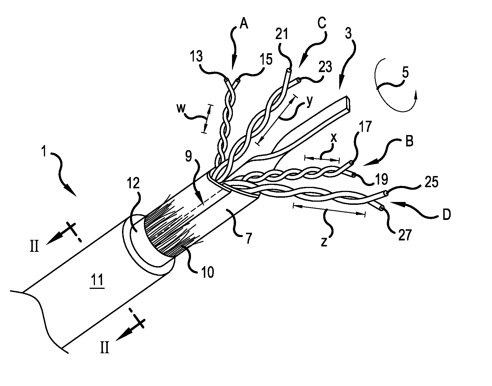
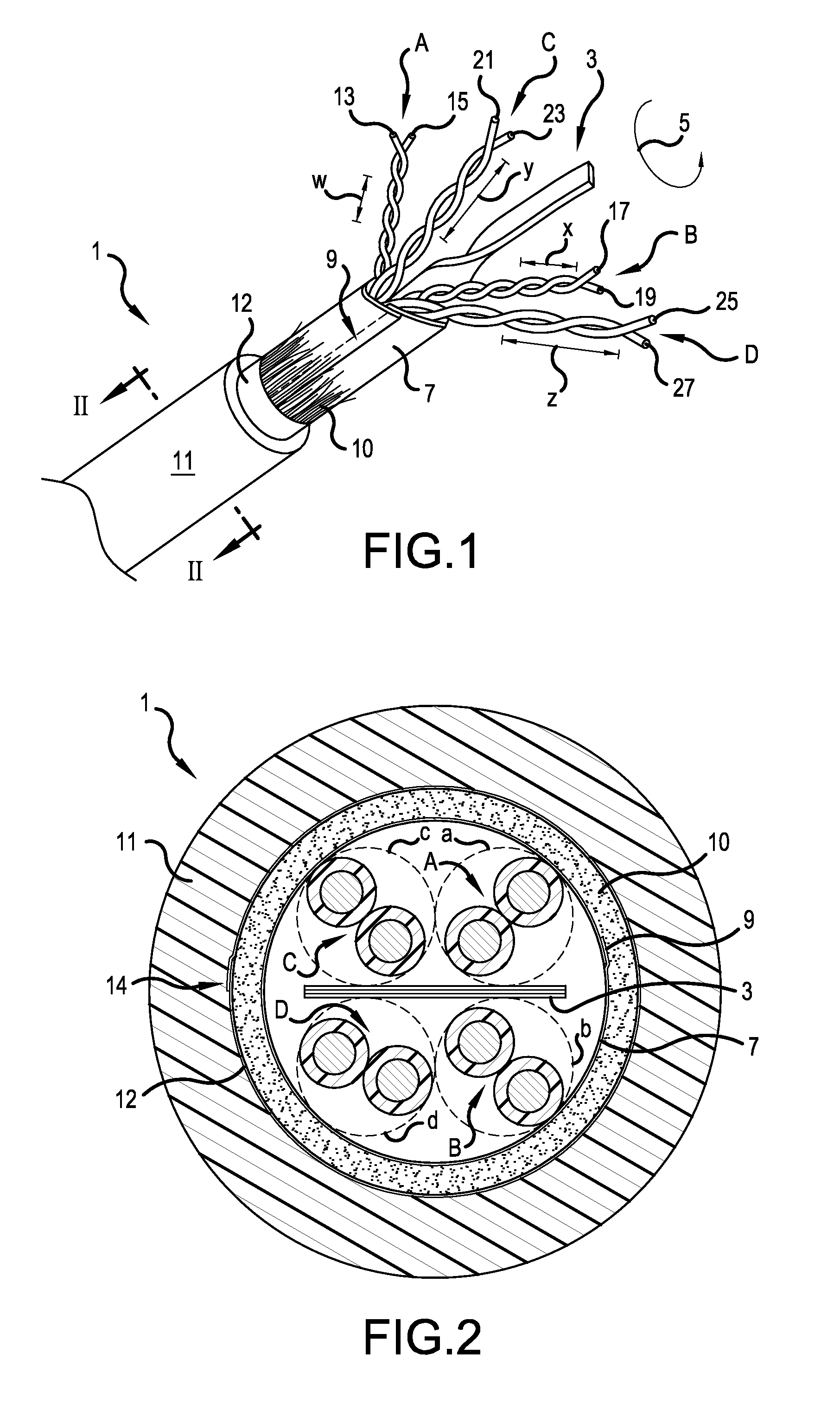
[0029]FIG. 1 is a perspective view of a twisted pair cable 1, in accordance with the present invention. FIG. 2 is a cross sectional view of the cable 1 taken along line II-II in FIG. 1. A cable core includes first, second, third and fourth twisted pairs A, B, C and D, respectively. The cable core is surrounded by a wrap or binder 7, such as a paper or Mylar® wrapper (biaxially-oriented polyethylene terephthalate), which is overlapping at area 9, and may optionally be adhered to itself in the overlapping area 9. A spacer 10, depicted as a plurality of fibers, surrounds the binder 7. The plurality of fibers may be formed of polymer strands, nylon strands, or other nonconductive natural or synthetic materials. The fibers may be loose or interconnected in the form of a tape or yard, such as in a lattice structure. One particularly well-suit material would be a polypropylene cable filler sold by Web Industries, Inc. under the trademark Superbulk™.

[0030]An outer shielding layer 12 surroun...

second embodiment

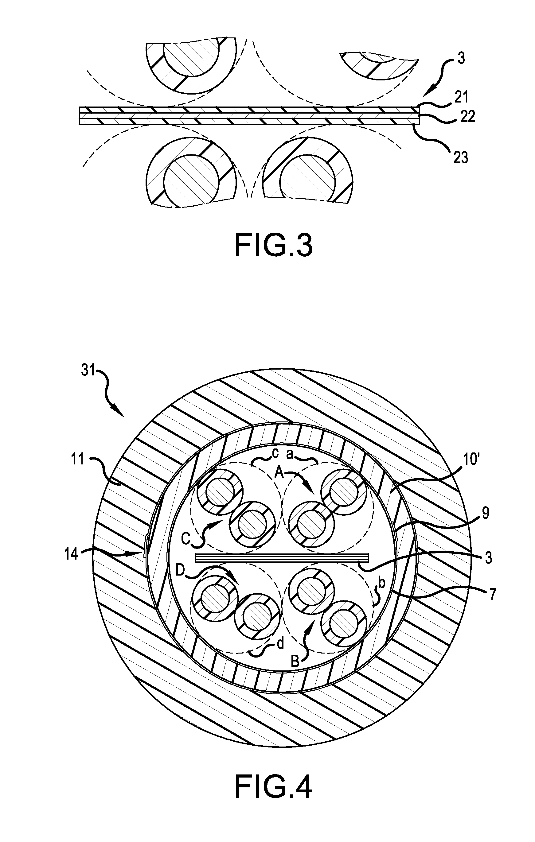
[0043]FIG. 4 is a cross sectional view, similar to FIG. 2, but showing a shielded, twisted pair cable 31, in accordance with the present invention. Like structures have been labeled with the same reference numerals as used in previous embodiment.

[0044]In the second embodiment, the spacer 10′ is now formed of a polymer material, as opposed to the fibrous material of the first embodiment of FIGS. 1 and 2. In a preferred embodiment, the polymer used to form the spacer 10′ is foamed, e.g., filled to some extent with trapped gas pockets. Once again, it is preferred that the spacer 10′ present a dielectric constant per unit volume, which is less than a dielectric constant per same unit volume of the material forming the jacket 11. For example, the spacer 10′ may be formed of a same polymer material as used to form the jacket 11, if the polymer material of the spacer 10′ is foamed to a greater extent than the polymer material used to form the jacket 11. All other aspects of the second embo...

third embodiment

[0045]FIG. 5 is a perspective view of a twisted pair cable 41, in accordance with the present invention. FIG. 6 is a cross sectional view of the cable 41 taken along line VI-VI in FIG. 5. Like structures have been labeled with the same reference numerals as used in previous embodiments.

[0046]In the third embodiment, the spacer 10′ is again formed of a polymer material, as depicted in the second embodiment. A drain wire 43 directly contacts the outer shielding layer 12. In the drawings, the drain wire 43 is located in direct contact with the inside surface of the outer shielding layer 12, however the drain wire 43 could also be located in direct contact with the outside surface of the outer shielding layer 12.

[0047]In the third embodiment, the separator 3′ is formed in cross section as a star-shaped or plus-shaped member. The separator 3′ separates the first and third twisted pairs A and C from the second and fourth twisted pairs B and D. However, the separator 3′ also separates the ...


PUM


Abstract

A cable includes a spacer surrounding a cable core. The cable core includes four twisted pairs. A separator is disposed amongst the twisted pairs. The separator may be formed with three layers, wherein a middle layer is conductive and outer layers are nonconductive. A jacket surrounds the spacer, and a shielding layer may reside between the jacket and the spacer. The spacer may be formed of plural fibers or a polymer. Preferably, the spacer presents a lower dielectric constant per unit volume than the jacket. The separator may have a tape shape or a plus shape.

Description

[0001]This application claims the benefit of U.S. Provisional Application No. 61 / 786,754, filed Mar. 15, 2013, which is herein incorporated by reference.BACKGROUND OF THE INVENTION[0002]1. Field of the Invention[0003]The present invention relates to a twisted pair cable for communication of high speed signals, such as a local area network (LAN) cable. More particularly, the present invention relates to a twisted pair cable having at least one conductive separator between twisted pairs within the cable, which reduces or eliminates the likelihood of transmission errors because of internal crosstalk, and at least one structure surrounding the cable core to reduce or eliminate the likelihood of transmission errors due to alien crosstalk.[0004]2. Description of the Related Art[0005]Along with the greatly increased use of computers for homes and offices, there has developed a need for a cable, which may be used to connect peripheral equipment to computers and to connect plural computers a...

Claims


Application Information

Patent Timeline
IPC IPC(8): H01B11/06
CPCH01B11/06H01B7/1875
Inventor HOPKINSON, WAYNE C.HAYES, TRENT M.
Owner COMMSCOPE INC
Why Eureka
Try Eureka