Cross-wing Twin-Fuselage Aircraft

a twin-fuselage aircraft and cross-wing technology, applied in the direction of aircraft crew accommodation, air-flow influencers, transportation and packaging, etc., can solve the problems of large-scale service of such aircraft, affecting the propulsion, structural design and materials of aircraft, and not being viable in time to meet near-term needs. , to achieve the effect of lowering the drag coefficien

Inactive Publication Date: 2014-09-18
MITCHELL JR LAWRENCE C
View PDF8 Cites 16 Cited by
  • Summary
  • Abstract
  • Description
  • Claims
  • Application Information

AI Technical Summary

Benefits of technology

[0025]FIG. 21 shows the disclosure aircraft (10) plane of symmetry (57) and that mature design can effectively take adv

Problems solved by technology

The largest of such aircraft now in service, are compromised in design by limits of ground facilities able to handle them.
Such aircraft are also placing strain on the technologies of propulsion, structural design, and materials.
New blended-wing aircraft are now being researched for the eventual replacement of tube-wing aircraft design, but they present their o

Method used


Image

  • Cross-wing Twin-Fuselage Aircraft
  • Cross-wing Twin-Fuselage Aircraft
  • Cross-wing Twin-Fuselage Aircraft

Examples


Embodiment Construction

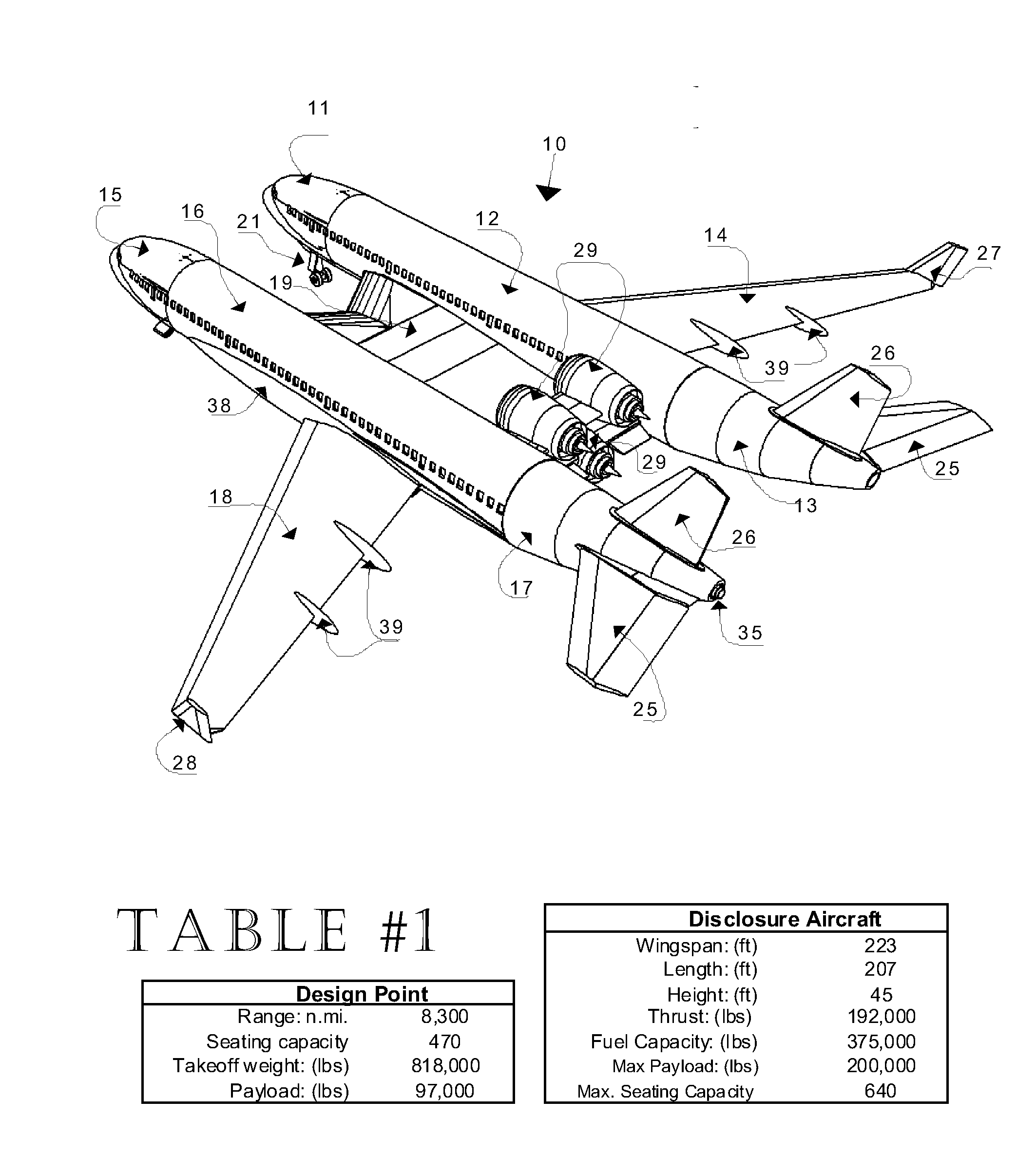
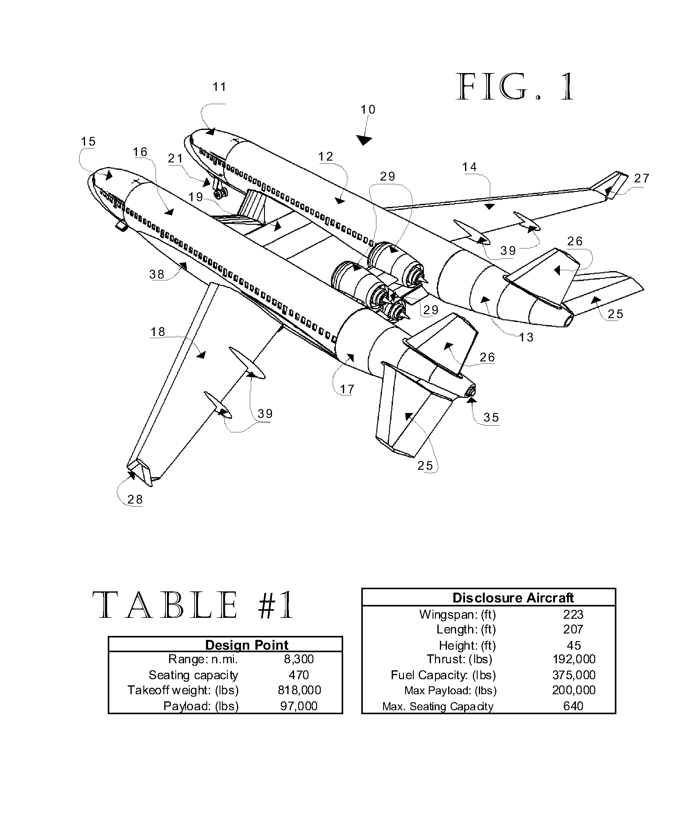
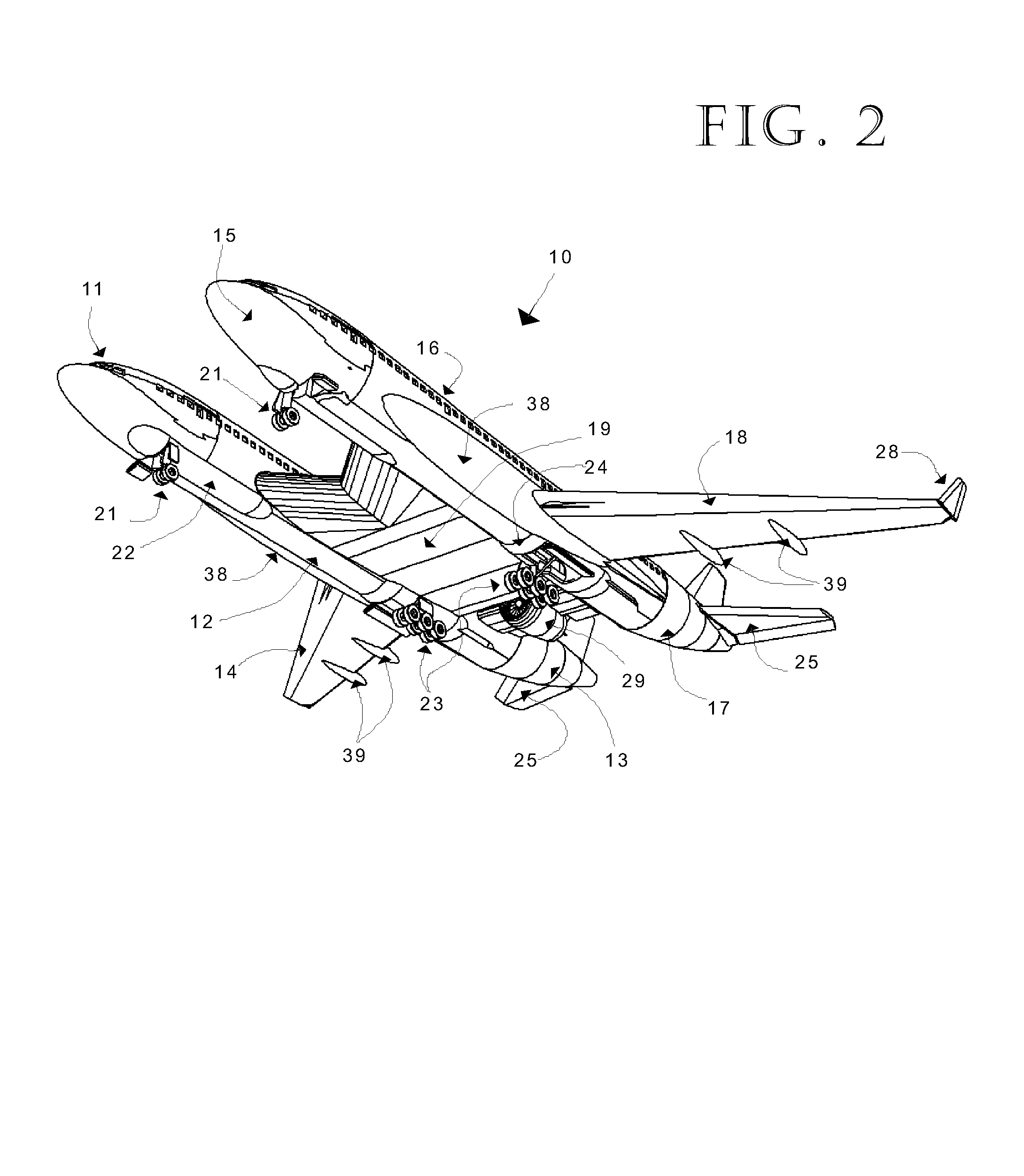
[0033]The aircraft (10) of this disclosure is presented with isometric views FIGS. 1-3, plan-views FIGS. 4-6, and cut-away detail views FIGS. 7-8.

[0034]Fuselage

[0035]The description of the fuselage concept is to show how very similar it is to the fuselage designs of the commercial airlines of today.

[0036]The fuselage of the disclosure aircraft (10) is just over 200 ft in length. The main deck provides seating accommodations for passengers and services FIG. 7. It is anticipated that passenger loading can be accommodated through two forward entrances (44,45) for each fuselage.

[0037]One of the twin fuselages, left or right, in the nose section (11 or 15) will contain the pilot cockpit cabin, equipped as other commercial aircraft, but with additional displays for scene visibility masked by the fuselage twin nose section, so viewing from the chosen cockpit need not compromised. The other fuselage nose section is available to provide passenger amenities, as airlines would so choose.

[0038]...


PUM


Abstract

A dimensionally size-efficient aircraft being of a twin-fuselage configuration that addresses long-range high-capacity passenger commercial or military application needs, unique in that propelling engines (two, three, or four engine arrangements) are centrally mounted aft of a central cross-wing section, that section addressing the structural requirements of fuselage attachment with a means of passage between fuselages, the outer main wings being free from hanging appendages, thereby enabling efficient aerodynamic-lift wing design, the configuration using a split stabilizer and a split vertical tail for stable aerodynamic control. Engine locations are biased high and aft with the central and outer wings providing ground noise abatement while in flight, passenger cabin noise low due to aft engine locations.
Efficiencies of operation derive from: 1) a low overall weight/revenue seat ratio, 2) large and adaptable passenger floor plans, 3) compatibility with existing ground terminal facilities, 4) multiple engine configuration selections enabled by this aircraft layout, both turbo-fan and turbo-prop, and 5) opportunities of growth within this configuration. It is a low wave-drag configuration that better approaches the cross-sectional frontal-area shape ideal for minimum drag at near transonic speeds. This disclosure represents a general design concept and not a specific point design.

Description

CROSS-REFERENCE TO RELATED APPLICATIONS[0001]Do not ApplyREFERENCES CITED[0002]US Patent documents6,913,228Jul. 05, 2005Lee et. Al.7,900,865Mar. 08, 2011Moore et. Al.8,157,204Apr. 12, 2012Wilby7,419,120Sep. 12, 2008Armand6,851,650Feb. 08, 2005Sankrithi6,666,406Dec. 13, 2003Sankrithi6,592,073Jul. 15, 2003Meekins6,047,923Apr. 11, 2000Lafferty5,893,535Apr. 13, 1999Hawley4,165,058Aug. 21, 1979Whitener3,913,871Oct. 21, 1975Miller3,907,218Sep. 23, 1975MillerBACKGROUND OF THE INVENTION[0003]Air traffic model forecasts suggest there is need for large capacity commercial aircraft to meet future air travel needs. Aircraft manufacturers already are in process of envisioning and designing new aircraft, and researching enabling technologies to meet anticipated demands. The largest of such aircraft now in service, are compromised in design by limits of ground facilities able to handle them. Such aircraft are also placing strain on the technologies of propulsion, structural design, and materials. ...

Claims


Application Information

Patent Timeline
IPC IPC(8): B64C39/04B64D11/00B64D27/12
CPCB64C39/04B64D27/12B64D11/00Y02T50/40
Inventor MITCHELL, JR., LAWRENCE C.
Owner MITCHELL JR LAWRENCE C
Why Eureka
Try Eureka