Vehicle rim with print graphics and methods of making

a technology of print graphics and bicycle wheels, applied in the field of bicycle wheels, can solve the problems of reducing the effectiveness of features, reducing the cost of creating tools for the manufacture of cfrp rims with surface features, and limited shapes, so as to achieve conservative weight savings, reduce substrate and processing steps, and achieve the effect of inherent efficiency

Inactive Publication Date: 2014-09-18
SRAM CORPORATION
View PDF20 Cites 8 Cited by
  • Summary
  • Abstract
  • Description
  • Claims
  • Application Information

AI Technical Summary

Benefits of technology

[0024]Another benefit of this deposition method and its inherent efficiency allows for the elimination of the adhesive backed substrate used in conventional methods. By eliminating the substrate and applying only the ink to the rim, a weight savings of greater than 30 grams can be achieved conservatively. Eliminating the substrate and the processing steps, e.g. die cutting, weeding, and assembly that follow a conventional printing process allow for a cost savings in excess of 90%.
[0025]Furthermore, this same printing method can be utilized as a means to coat with a pr

Problems solved by technology

Furthermore, the process of creating the tools to manufacture CFRP rims with surface features can be expensive.
Unfortunately, the printing technology commonly in practice tends to cover up pre-existing surface features, which obscures and may significantly reduce the effectiveness of the features.
The current methods for industrially marking a rim as briefly noted above have technical disadvantages, some of which are described below:Printed decal with pressure sensitive adhesive, i.e. a self-adhesive sticker—arguably the most common method of marking—graphic image size can be limited due to the adhesive tack of the substrate; graphic shapes are limited by the complexity of die cutting the substrate; decal substrate cannot adequately conform to non-smooth surface features; substrate has significant mass; relative hardness of the substrate is inadequate to provide durability; adhesive bond is not permanent.Solvent applied decal wi

Method used


Image

  • Vehicle rim with print graphics and methods of making
  • Vehicle rim with print graphics and methods of making
  • Vehicle rim with print graphics and methods of making

Examples


Embodiment Construction

[0039]Embodiments of the invention will herein be described with reference to the drawings. It will be understood that the drawings and descriptions set out herein are provided for illustration only and do not limit the invention as defined by the claims appended hereto and any and all their equivalents. For example, the terms “first” and “second,”“front” and “rear,” or “left” and “right” are used for the sake of clarity and not as terms of limitation. Moreover, the terms refer to bicycle mechanisms conventionally mounted to a bicycle and with the bicycle oriented and used in a standard fashion unless otherwise indicated.

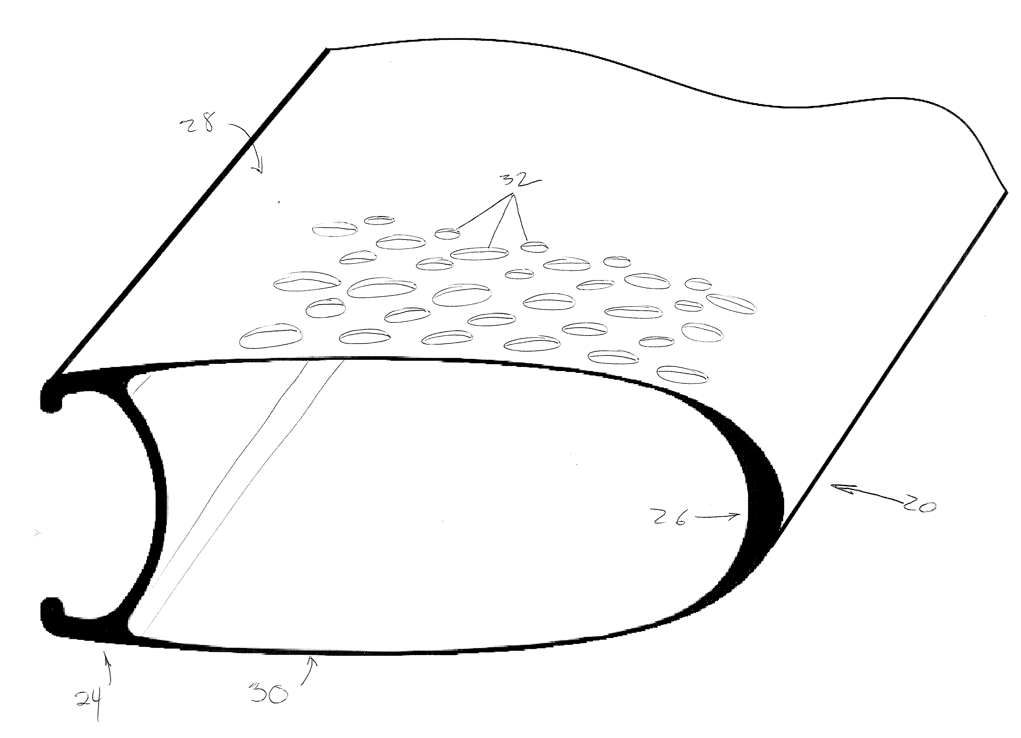
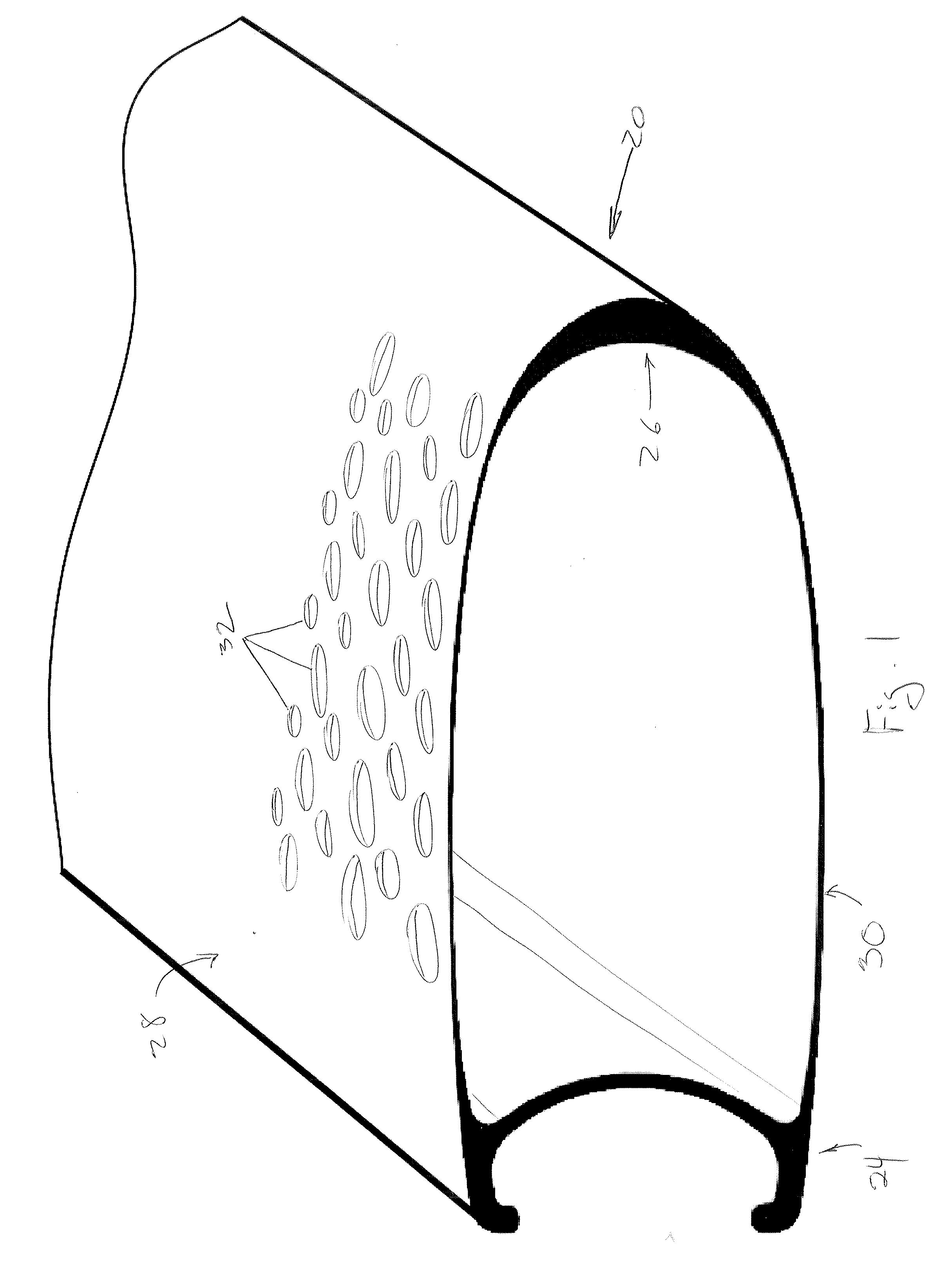
[0040]FIGS. 1 and 3 show one embodiment of a rim 20 for a bicycle to which a non-contact printed graphic may be applied. The rim 20 includes a tire-engaging portion 24 located at the outer perimeter of the rim, an inner perimeter portion 26 located radially inwardly from the tire-engaging portion, and a pair of sidewalls 28, 30 extending in a radial direction betwee...


PUM

PropertyMeasurementUnit
Angleaaaaaaaaaa
Distanceaaaaaaaaaa
Areaaaaaaaaaaa

Abstract

A rim is provided for a bicycle wheel having an axis about which the wheel rotates and a center plane normal to the axis, including a tire-engaging portion located at an outer perimeter of the rim. An inner perimeter portion is located radially inwardly from the tire-engaging portion. The rim includes a first sidewall and a second sidewall spaced from the first sidewall. The first and second sidewalls extend between the tire-engaging and inner perimeter portions. An image receiving area is located on each of the first and second sidewalls and a non-contact printed graphic is disposed on at least some of the image receiving area.

Description

BACKGROUND OF THE INVENTION[0001]The invention relates to bicycle wheels. In particular, the invention is directed to rims for bicycle wheels, and the like, which are provided with non-contact printed graphics and the like.[0002]It has become commonplace to mark bicycle rims with various indicia, images, words and other graphics. With the widespread acceptance of deep-section rims among professional racers and amateurs alike, manufacturers have recognized the “billboard” opportunities presented by the significant amount of rim area. A notable example of such a rim is exemplified in U.S. Pat. No. 7,114,785 directed to a “disc” wheel for a bicycle. The patent illustrates both carbon fiber reinforced plastic construction and surface features.[0003]Bicycle rims, for example carbon fiber reinforced plastic (CFRP) bicycle rims, have increasingly been labeled, marked or coated in a number of conventional methods with conventional materials. With respect to marking a rim graphically, conven...

Claims


Application Information

Patent Timeline
IPC IPC(8): B44C1/00B60B21/00
CPCB60B21/00B44C1/00B60B2310/648B60B2310/658B41M5/0047B41M5/0064B41M5/0082B41M7/0081B60B5/02B60B21/025F15D1/003B60B2310/616B60B2310/656B60B2360/341B60B2900/111B60B2900/112B60B2900/1216B60B2900/572B60Y2200/134B60B7/0053B60B7/0066B60B2310/661B60B1/003B60B7/0006B60B7/0033B60B7/063B60B21/04B60B2900/325B60B2900/00Y02T10/86Y02T10/88
Inventor BRADY, PATRICKWESLING, KEVIN
Owner SRAM CORPORATION
Why Eureka
Try Eureka