Soft magnetic core and motor including the same

Inactive Publication Date: 2014-09-18
SAMSUNG ELECTRO MECHANICS CO LTD
View PDF4 Cites 8 Cited by
  • Summary
  • Abstract
  • Description
  • Claims
  • Application Information

AI Technical Summary

Benefits of technology

The patent text describes improvements to a soft magnetic core used in motors. These improvements enhance the core's electrical properties, resulting in stronger magnetic fields and increased intensity. The text also describes a soft magnetic core that allows for higher magnetic flux density and the resulting motor's increased performance.

Problems solved by technology

However, in the case of manufacturing a soft magnetic core by stacking steel plates, it may be difficult to manufacture a product having a relatively complicated three-dimensional shape and a large amount of scrap loss may be generated.
In the case of a soft magnetic core formed of the soft magnetic composite according to the related art, since the powder particles are only molded through the pressurization thereof and are not in a state in which sintering has been undertaken thereon, the soft magnetic composite core may easily broken due to an external impact.
Particularly, in the case of a core for a motor, when performing winding work, the possibility that a portion of the core will be broken may be high.
In the case of a general soft magnetic composite core for low core loss, there is a limit to increase molding density at the time of manufacturing thereof.
Therefore, a level of density needed to be realized in products may not be able to be implemented.
Further, due to a decrease in frictional force between powder particles and a decrease in frictional force between the powder particles and a surface of a molding apparatus, it may be difficult to secure a sufficient molding density value.
In addition, in the case of increasing molding pressure in order to secure the molding density, the insulating coating layer is broken and cracks, and the like may occur in a mold wall and the molding apparatus, such that a lifespan of the mold may be decreased and several characteristics of the molding body are degraded.
At the time of applying this core to the motor, since characteristics and efficiency of the motor are decreased, the limitation on the use thereof according to a usable frequency region is increased.
In addition, in the case in which the core is manufactured using a Fe—Si or an Fe—Si—B based amorphous powder, since the amorphous powder particles themselves are easily broken as compared to pure iron powder particles, the molding density and saturation magnetic flux density thereof may be low.
In addition, since the intensity is not high, it is difficult to apply the amorphous powder to the core of a small motor such as a hard disk drive (HDD).
Patent Document 1 discloses a metal magnetic particle and an insulation film coating the metal magnetic particle, but does not disclose a method for increasing the intensity and electrical properties of the core.

Method used


Image

  • Soft magnetic core and motor including the same
  • Soft magnetic core and motor including the same
  • Soft magnetic core and motor including the same

Examples


Embodiment Construction

[0051]Hereinafter, embodiments of the present invention will be described in detail with reference to the accompanying drawings. The invention may, however, be embodied in many different forms and should not be construed as being limited to the embodiments set forth herein. Rather, these embodiments are provided so that this disclosure will be thorough and complete, and will fully convey the scope of the invention to those skilled in the art. In the drawings, the shapes and dimensions of elements may be exaggerated for clarity, and the same reference numerals will be used throughout to designate the same or like elements.

[0052]Motor

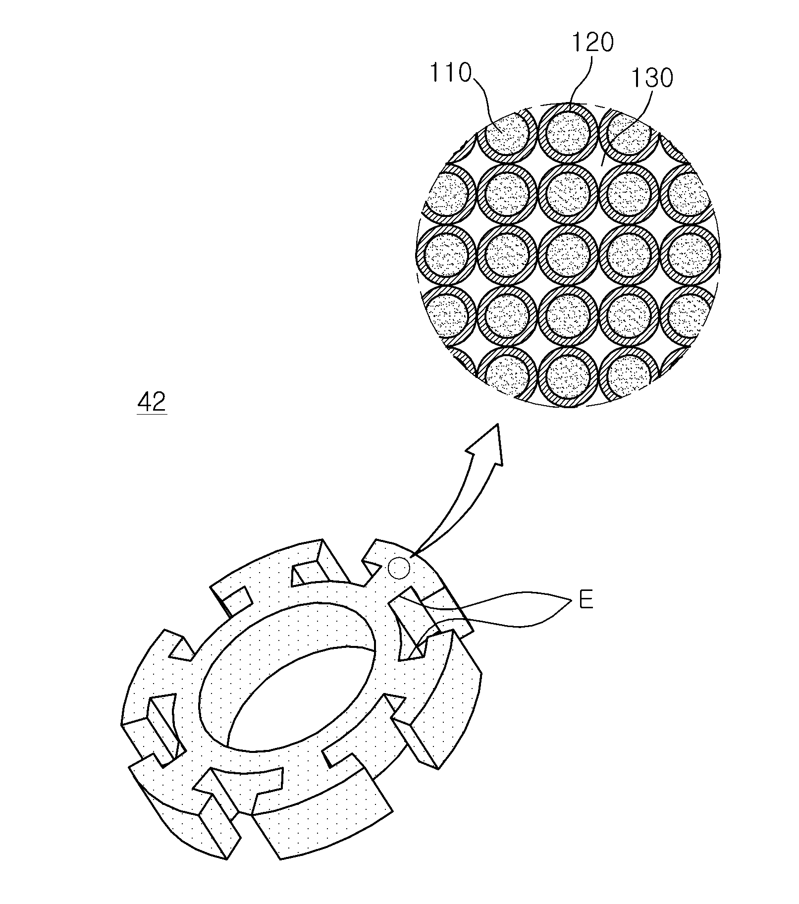
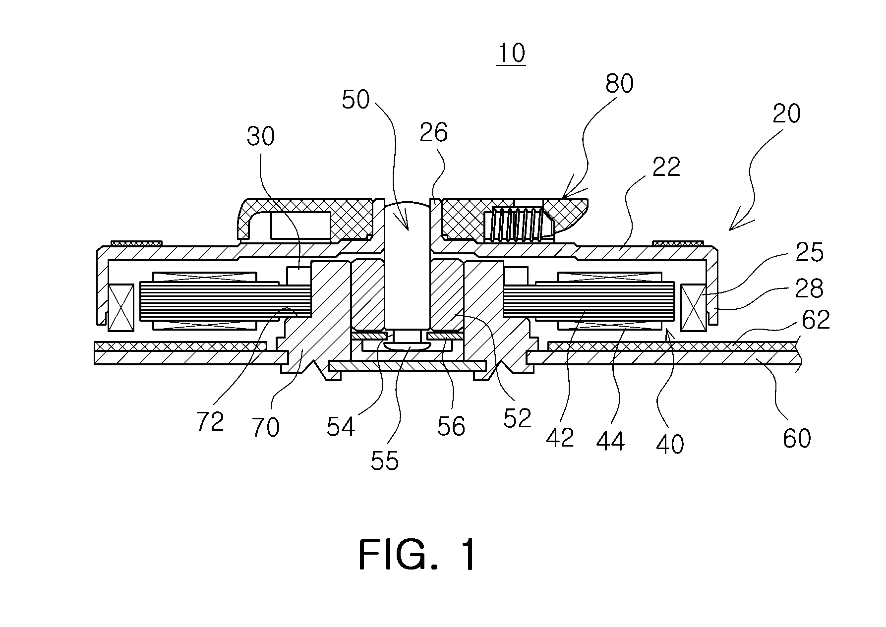
[0053]FIG. 1 is a schematic perspective view illustrating a motor including a soft magnetic core according to an embodiment of the present invention.

[0054]Referring to FIG. 1, a motor 10 according to an embodiment of the present invention, a spindle motor applied to an optical disc drive for rotating a disc, may mainly include a rotor 20 and a stator 40.

[...


PUM

PropertyMeasurementUnit
Thicknessaaaaaaaaaa
Thicknessaaaaaaaaaa
Diameteraaaaaaaaaa

Abstract

There is provided a soft magnetic core including: soft magnetic powder particles having an insulating coating layer formed on surfaces thereof and metal powder particles positioned between the soft magnetic powder particles.

Description

CROSS-REFERENCE TO RELATED APPLICATIONS[0001]This application claims the priority of Korean Patent Application No. 10-2013-0027532 filed on Mar. 14, 2013, in the Korean Intellectual Property Office, the disclosure of which is incorporated herein by reference.BACKGROUND OF THE INVENTION[0002]1. Field of the Invention[0003]The present invention relates to a soft magnetic core and a motor including the same, and more particularly, to a soft magnetic core having improved electrical properties and magnetic flux density and a motor including the same.[0004]2. Description of the Related Art[0005]Generally, a soft magnetic material has had various applications, for example, in an inductor core, in a stator, in a rotor, and in an actuator of an electrical apparatus such as a motor, in a sensor, and in a transformer core.[0006]According to the related art, a method, in which processed steel plates are stacked in several layers and are then fixed to one another so as to be integrated has been ...

Claims


Application Information

Patent Timeline
IPC IPC(8): H01F3/08H02K1/00B22F1/102B22F1/16
CPCH02K1/00H01F3/08H02K1/02H02K1/04B22F1/102B22F1/16H01F41/02H01F1/20
Inventor KIM, HAK KWANAN, SUNG YONGPARK, NO ILCHOI, DONG HYEOK
Owner SAMSUNG ELECTRO MECHANICS CO LTD
Why Eureka
Try Eureka