Spark plug for internal combustion engines and mounting structure for the spark plug
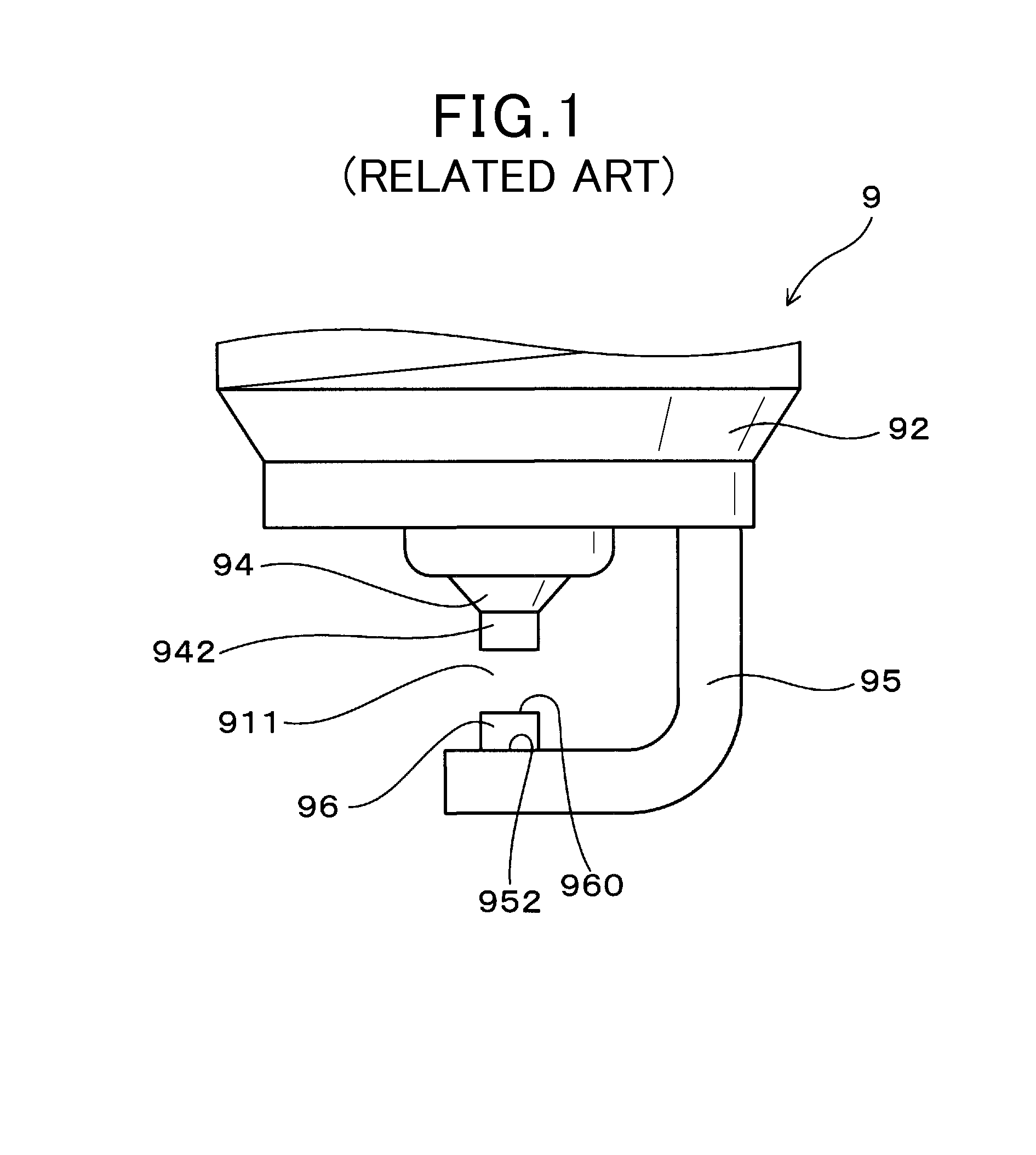
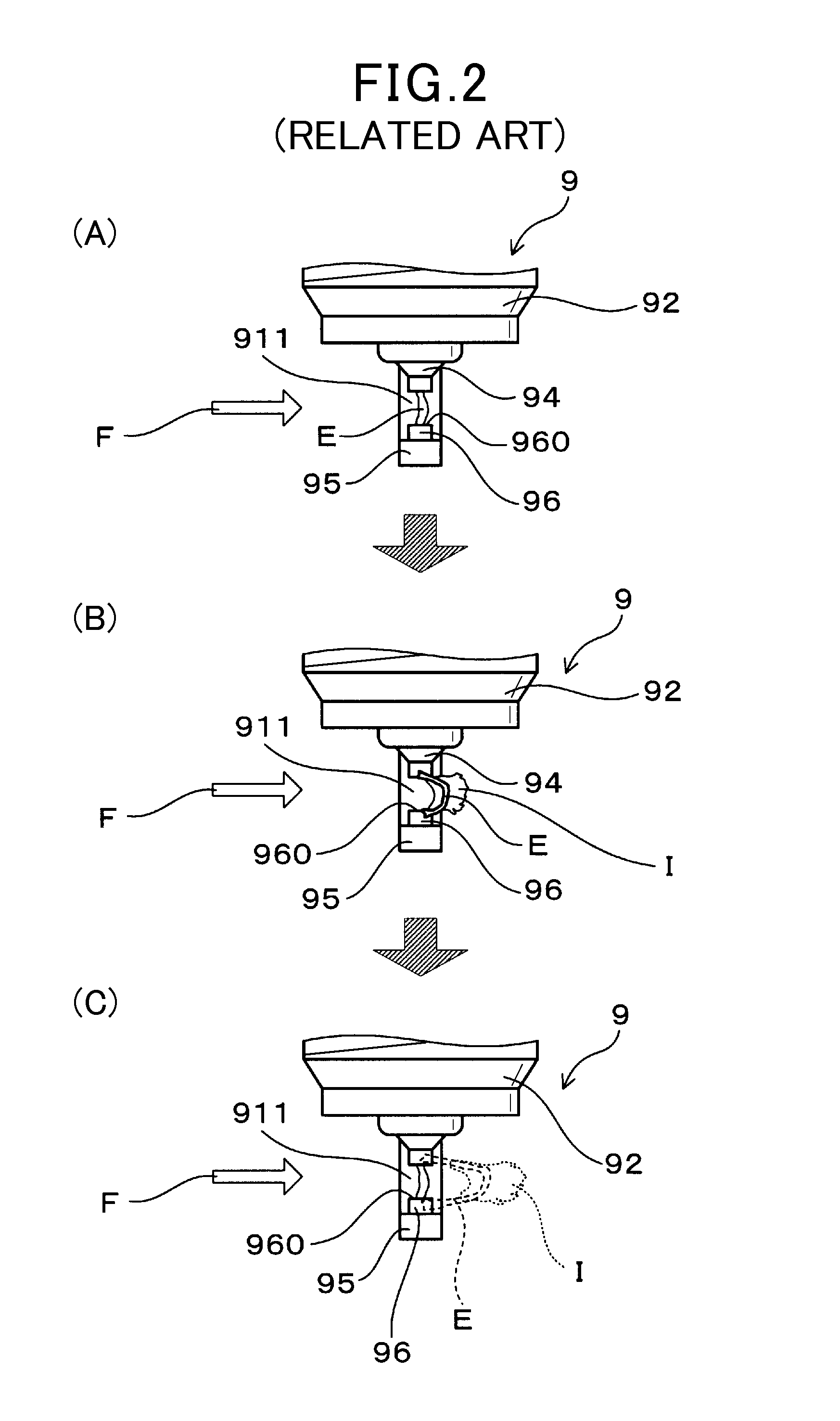
a technology for internal combustion engines and mounting structures, which is applied to spark plugs, machines/engines, mechanical equipment, etc., can solve the problems of affecting the ignitability of the spark plug, the proportion tends to be disproportionately worn out, and the life of the spark plug is problematically shortened, so as to minimize the expansion of the range of wear and minimize the disproportionate wear of the projection portion. , the effect of prolonging the life of the spark plug
- Summary
- Abstract
- Description
- Claims
- Application Information
AI Technical Summary
Benefits of technology
Problems solved by technology
Method used
Image
Examples
first embodiment
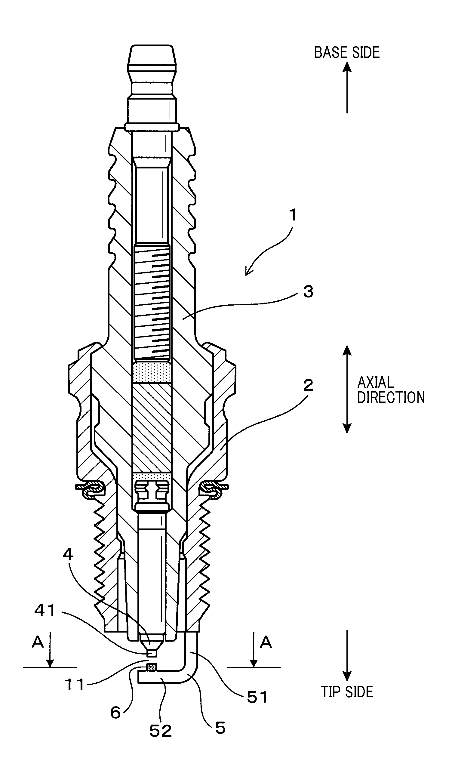
[0041]Referring to FIGS. 3 to 8, a spark plug of an embodiment is described.
[0042]As shown in FIG. 3, a spark plug 1 of the present embodiment includes: a cylindrical housing 2; a cylindrical insulation porcelain 3 held inside the housing 2; a center electrode 4 held inside the insulation porcelain 3 such that a tip portion is projected; and a ground electrode 5 connected to the housing 2 and having an opposing portion 52 that faces the center electrode 4 in an axial direction of the plug (longitudinal direction of the spark plug 1: see FIG. 3) to form a spark discharge gap 11 between the center electrode 4 and the ground electrode 5.
[0043]In the opposing portion 52 of the ground electrode 5, a projection portion 6 is arranged being projected toward the spark discharge gap 11.
[0044]As shown in FIG. 4, the projection portion 6 is in a specific shape. The projection portion 6 has a cross section perpendicular to the axial direction of the plug, and the cross section has a contour 60 t...
second embodiment
[0068]As shown in FIGS. 9 to 11, in the present embodiment, the projection portion 41 provided at the tip portion of the center electrode 4 is also in the specific shape similar to the projection portion 6 of the ground electrode 5.
[0069]In the present embodiment, as shown in FIGS. 10 and 11, both of the projection portion 41 of the center electrode 4 and the projection portion 6 of the ground electrode 5 have a cross section perpendicular to the axial direction of the plug, the cross section being in the specific shape shown in the first embodiment (see FIG. 4).
[0070]In a state where the spark plug 1 of the present embodiment is mounted to the combustion chamber 70 of the internal combustion engine 7 (see FIG. 6), the first region B of each of the projection portion 41 and the projection portion 6 is located upstream of the second region C with respect to the flow F. At the same time, the minimum curvature radius portion 61 in each of the projection portions is oriented to an upstr...
third embodiment
[0074]As shown in FIG. 12, in the present embodiment, the projection portion 6 is arranged such that the first straight line L1 will obliquely intersect the extending direction of the opposing portion 52 of the electrode 5.
[0075]The projection portion 6 of the present embodiment is arranged such that the first straight line L1 intersects the extending direction of the opposing portion 52 (broken line L5) of the ground electrode 5 at an angle of 45°.
[0076]The rest other than the above is similar to the first embodiment.
[0077]As shown in FIG. 12, in the present embodiment as well, the flow F that flows toward the spark discharge gap 11 is prevented from being blocked by the ground electrode 5. At the same time, the second region C is ensured to be located downstream in the flow F and the first region B is ensured to be located upstream in the flow F. Specifically, for example, when the spark plug 1 is mounted to the combustion chamber 70 of the internal combustion engine 7 so that the...
PUM
 Abstract
Description
Claims
Application Information
 - R&D
- Intellectual Property
- Life Sciences
- Materials
- Tech Scout
- Unparalleled Data Quality
- Higher Quality Content
- 60% Fewer Hallucinations
Browse by: Latest US Patents, China's latest patents, Technical Efficacy Thesaurus, Application Domain, Technology Topic, Popular Technical Reports.
© 2025 PatSnap. All rights reserved.Legal|Privacy policy|Modern Slavery Act Transparency Statement|Sitemap|About US| Contact US: help@patsnap.com


