Method for Satellite Beacon Signal Detection and Antenna Alignment

Inactive Publication Date: 2014-09-18
ASC SIGNAL CORP
View PDF1 Cites 6 Cited by
  • Summary
  • Abstract
  • Description
  • Claims
  • Application Information

AI Technical Summary

Problems solved by technology

Satellite communication systems typically utilize high gain ground antennas to overcome the limited power available for the satellite transmitter and high path losses due to the large distances.
However, this fixed “beacon” signal is transmitted at a much lower power level than the signals carrying the information because of the limited power available on an orbiting satellite.
This can make receiving the beacon signal d

Method used


Image

  • Method for Satellite Beacon Signal Detection and Antenna Alignment
  • Method for Satellite Beacon Signal Detection and Antenna Alignment
  • Method for Satellite Beacon Signal Detection and Antenna Alignment

Examples


Example

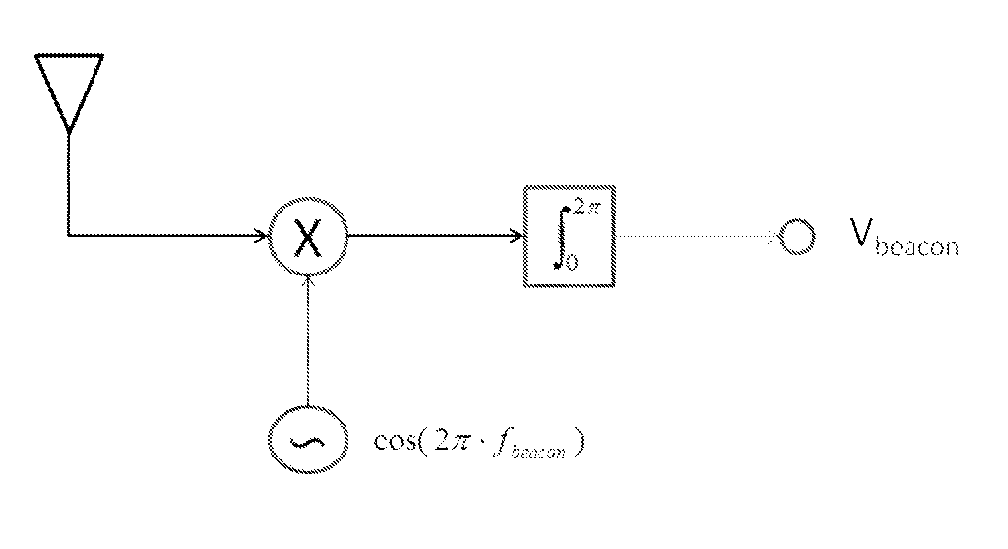
[0014]Satellite beacon signals are typically fixed in amplitude and / or frequency and may also be slowly modulated. Therefore, a copy of the desired satellite beacon signal may be stored locally and / or generated on demand. The inventor has recognized that by multiplying the received satellite signal with a local copy of the beacon signal, a constant dc term “A / 2” is obtained, only if the received signal includes a component of the beacon signal, otherwise the resulting products contain only sinusoidal terms. When integrated over time the sinusoidal terms tend to zero while the constant term grows. This dc term may be used as an antenna alignment indicator, even where the signal level of the beacon signal is below the noise floor of the rf environment the beacon signal is transmitted within.

[0015]For example:

A·cos(2π·fbeacon(xmit)·t)*cos(2π·fbeacon(local)·t)=A2cos(2π·(fbeacon(xmit)-fbeacon(local))·t)+A2cos(2π·(fbeacon(xmit)-fbeacon(local))·t)

if this is integrated over one period (for ...


PUM


Abstract

A method for detecting a beacon signal, by receiving a beacon signal and processing the beacon signal with respect to a local copy of the beacon signal. The processing including multiplying the beacon signal with a local copy of the beacon signal and integrating the result to generate a background noise filtered beacon signal output. The beacon signal output may be utilized to align an antenna with the beacon signal by adjusting alignment until the beacon signal output is either maximized or minimized, depending upon the function applied.

Description

BACKGROUND[0001]1. Field of the Invention[0002]This invention relates to satellite antenna tracking. More particularly, the invention relates to antenna alignment with a satellite via satellite beacon signal processing in combination with a local copy of the beacon signal, enabling monitoring of the received beacon signal level by an antenna, for example, below a noise floor of a receiver.[0003]2. Description of Related Art[0004]Satellite communication systems typically utilize high gain ground antennas to overcome the limited power available for the satellite transmitter and high path losses due to the large distances.[0005]While the high gain of the ground antennas allows the received signals to be detected even at low transmission power levels, the high gain of these antennas typically results in a very narrow main lobe antenna signal pattern characteristic. Therefore, aligning the antenna's main beam with the satellites position in orbit is a critical aspect of the communication...

Claims


Application Information

Patent Timeline
IPC IPC(8): H01Q3/00
CPCH01Q3/00H01Q1/1257
Inventor ELLIS, THOMAS J.
Owner ASC SIGNAL CORP
Why Eureka
Try Eureka