Partitioned aperture wavefront imaging method and system

a partitioned aperture wavefront and imaging system technology, applied in the field of partitioned aperture wavefront imaging system and a, can solve the problems of inability to retrieve absolute wavefront phase from a single pc or dic image, less straightforward phase measurement, and inability to provide quantitative images of wavefront phase, etc., to achieve improved spatial resolution, simple optical design, and higher quality optical lenses

Inactive Publication Date: 2014-09-18
TRUSTEES OF BOSTON UNIV
View PDF8 Cites 49 Cited by
  • Summary
  • Abstract
  • Description
  • Claims
  • Application Information

AI Technical Summary

Benefits of technology

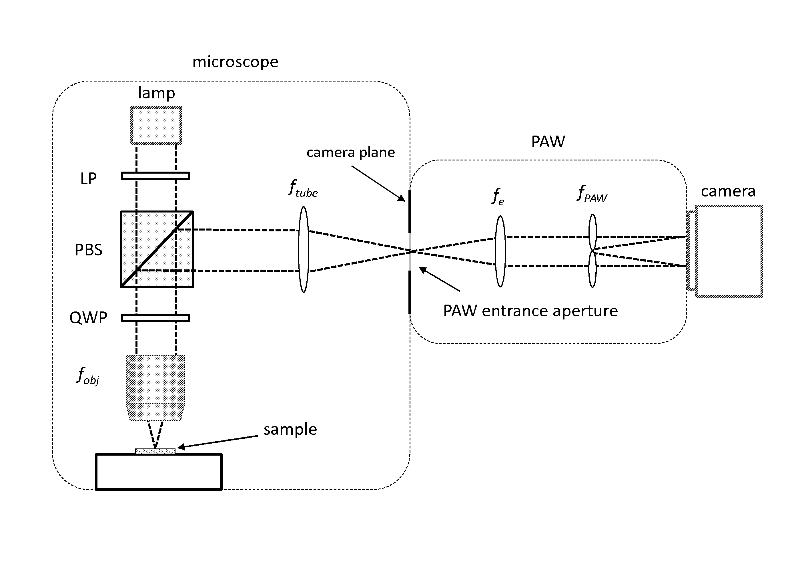
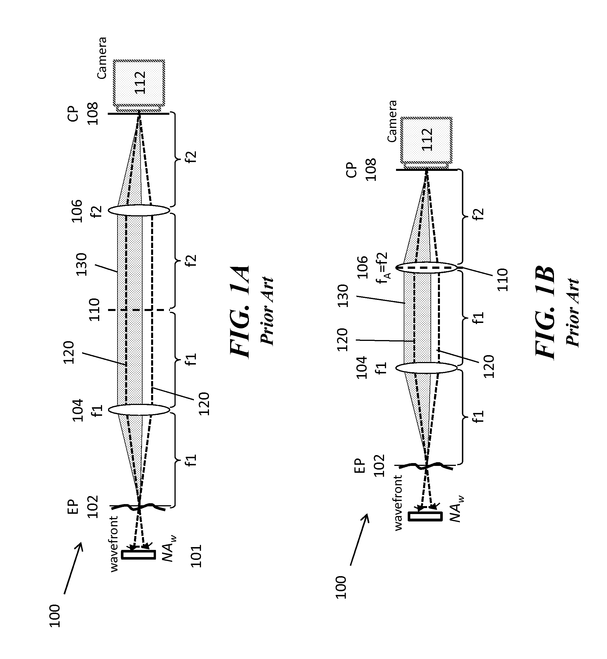
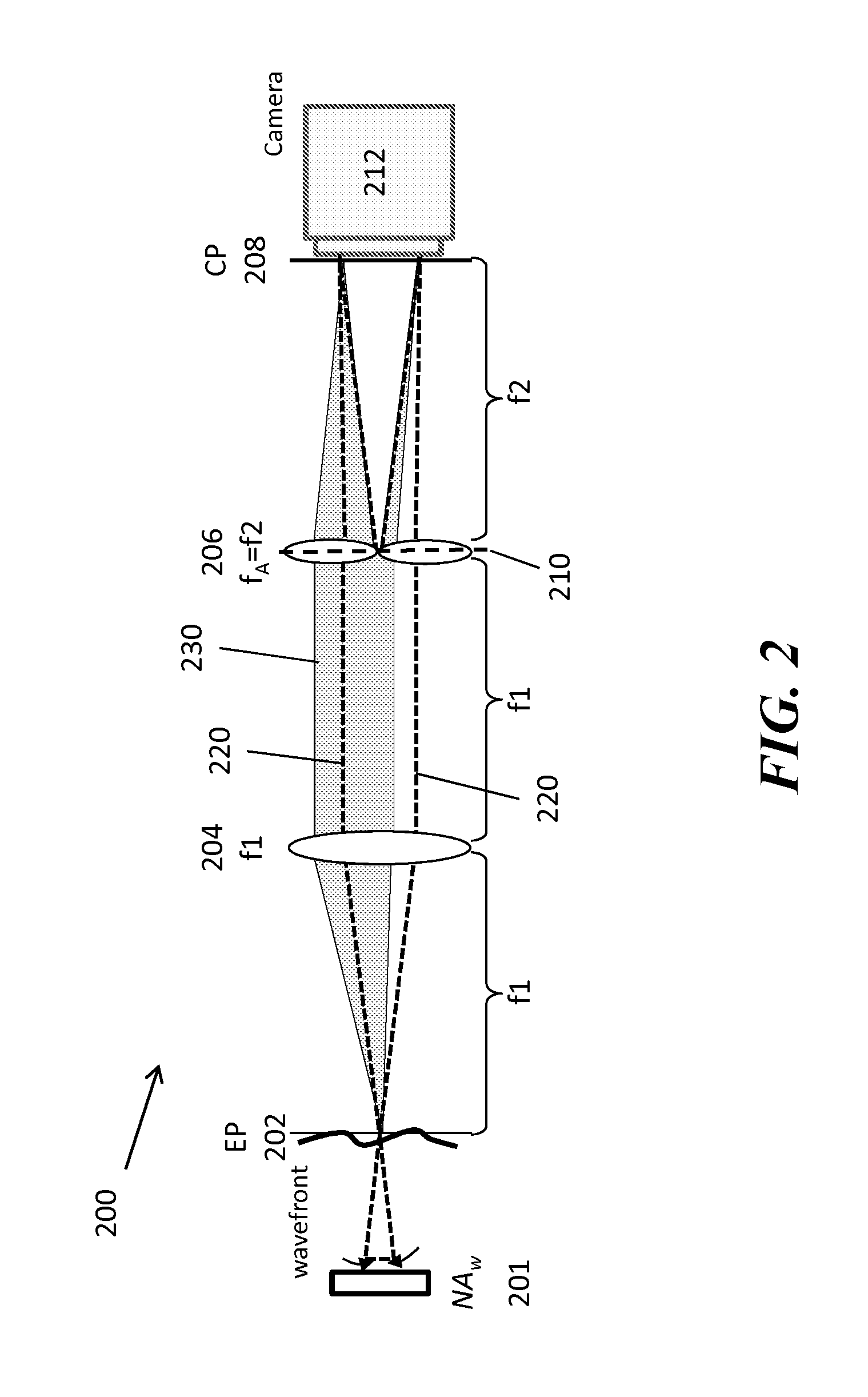
[0018]The PAW imaging system according to the invention can record both the wavefront amplitude and tilt, but these are encoded in a specific manner. Rather than dividing the camera sensor into many coarse pixel blocks, the camera sensor can be divided into a few (e.g., 3, 4 or 5) partitions. Amplitude information can be encoded within each partition with single pixel resolution; tilt information can be encoded across different partitions. The PAW imaging system can provide enhanced spatial resolution (for the same number of camera pixels) and simpler optical design. In particular, the PAW imaging system can use higher quality optical lenses because it does not require a lenticular screen as used in prior art devices.
[0019]Other advantages of the PAW imaging system according to the invention include that 1) the PAW imaging system uses oblique detection rather than oblique illumination, 2) the PAW imaging system acquires all oblique images simultaneously, 3) the PAW imaging system can be based on a 2f or a 3f or a 3f telecentric imaging geometry, 4) the PAW imaging system can be more light efficient than prior art system, and 5) the PAW imaging system can be implemented in a device that requires no moving parts, 6) the PAW imaging system can be insensitive to light polarization, 7) the PAW imaging system can be achromatic.
[0020]In accordance with implementations of the invention, one or more of the following capabilities may be provided. The PAW imaging system according to embodiments of the invention provides a high speed (single shot) and high resolution imaging system that produces quantitative amplitude and phase data about a wavefront. In addition, the PAW imaging system according to the invention can be implemented in a low cost, versatile (can be coupled to existing imaging devices), highly efficient (e.g., light efficient, works with un-collimated light and broadband light) system that provides a high dynamic range in a small robust package.

Problems solved by technology

The measurement of phase is less straightforward.
One variant if DIC is called PlasDIC, which is available from Carl Zeiss Microscopy, LLC, Thornwood, N.Y. However, these devices only provide non-quantitative images of wavefront phase, meaning that the absolute wavefront phase cannot be retrieved from a single PC or DIC image.
A variety of oblique illumination and / or detection techniques also provide phase gradient contrast, but these are also non-quantitative.
It is thus not possible to reconstruct the physical attributes in a sample associated with phase (or amplitude).
However, while SH wavefront sensors exhibit exquisite phase resolution, they exhibit poor spatial resolution.
A sequence of images with at least 3 phase steps must be acquired to obtain quantitative phase contrast, meaning that image acquisition speed is reduced by a factor of three, and imaging is sensitive to motion artifacts.
The numerical algorithms in these techniques are fairly sophisticated and sensitive to noise.

Method used


Image

  • Partitioned aperture wavefront imaging method and system
  • Partitioned aperture wavefront imaging method and system
  • Partitioned aperture wavefront imaging method and system

Examples


Embodiment Construction

[0042]It should be understood that this invention is not limited to the particular embodiments, methodologies, or protocols, described herein and as such can vary from the illustrative embodiments provided. The terminology used herein is for the purpose of describing the particular embodiments only, and is not intended to limit the scope of the present invention, which is defined solely by the claims.

[0043]As used herein and in the claims, the singular forms include the plural and vice versa unless the context clearly indicates otherwise. Other than in the operating examples, or where otherwise indicated, all numbers expressing quantities used herein should be understood as modified in all instances by the term “about.”

[0044]All publications identified are expressly incorporated herein by reference for the purpose of describing and disclosing, for example, the methodologies described in such publications that might be used in connection with the present invention. These publications...


PUM


Abstract

A partitioned aperture wavefront imaging system includes an imaging system comprising a partitioned aperture lens array positioned at the aperture plane or Fourier plane between the entrance plane and camera plane of an imaging system. The partitioned aperture lens array can include 2 or more off-axis lenses symmetrically distributed about an optical axis, and adapted to produce simultaneously at the camera plane at least two images of an object, or intermediate image of an object, presented at the entrance plane. Preferably, the partitioned aperture lens array includes from 3 to 5 off-axis lenses and produces 3 to 5 images at the camera plane from which phase and amplitude information about the light field can be determined. The partitioned aperture wavefront imaging system provides enough information about the light field presented at the entrance plane to enable reconstruction of the light field at other planes relative to the entrance plane.

Description

CROSS-REFERENCE TO RELATED APPLICATIONS[0001]This application claims benefit under 35 U.S.C. §119(e) of the U.S. Provisional Application No. 61 / 675,113, filed on Jul. 24, 2012, the contents of which are herein incorporated by reference in its entirety.STATEMENT REGARDING FEDERALLY SPONSORED RESEARCH[0002]This invention was made with US Government support under contract NIH R21-EB013381 awarded by the US National Institutes of Health. The US Government has certain rights in this invention.REFERENCE TO MICROFICHE APPENDIX[0003]Not ApplicableBACKGROUND[0004]1. Technical Field of the Invention[0005]The present invention is directed to a partitioned aperture wavefront imaging system and a method for measuring amplitude and phase of a light field at a plane. Methods and systems according to the invention enable the production of high resolution images and the ability to reconstruct the light field at other planes displaced from the measurement plane.[0006]2. Description of the Prior Art[0...

Claims


Application Information

Patent Timeline
Patent Type & Authority Applications(United States)
IPC IPC(8): G02B21/36
CPCG02B21/361G01J9/00
Inventor MERTZ, JEROME CHARLESCHU, KENGYEH KENPARTHASARATHY, ASHWIN
Owner TRUSTEES OF BOSTON UNIV
Why Eureka
Try Eureka