Multilayer plasmon generator
a multi-layer, generator technology, applied in the field of plasmon generators, can solve the problems of increasing the coercivity of the recording medium, reducing the thermal stability of the magnetization of the magnetic fine particles, and difficulty in performing data writing with the existing magnetic head, and achieves the effect of high reliability
- Summary
- Abstract
- Description
- Claims
- Application Information
AI Technical Summary
Benefits of technology
Problems solved by technology
Method used
Image

Examples
first embodiment
[0050]Preferred embodiments of the present invention will now be described in detail with reference to the drawings. First, reference is made to FIG. 5 and FIG. 6 to describe the configuration of a thermally-assisted magnetic recording head according to a first embodiment of the invention. The thermally-assisted magnetic recording head according to the present embodiment includes a plasmon generator according to the present embodiment. FIG. 5 is a cross-sectional view showing the configuration of the thermally-assisted magnetic recording head. FIG. 6 is a front view showing the medium facing surface of the thermally-assisted magnetic recording head.
[0051]The thermally-assisted magnetic recording head according to the present embodiment is for use in perpendicular magnetic recording, and is in the form of a slider to fly over the surface of a rotating recording medium. When the recording medium rotates, an airflow passing between the recording medium and the slider causes a lift to b...
second embodiment
[0119]A plasmon generator and a thermally-assisted magnetic recording head according to a second embodiment of the invention will now be described with reference to FIG. 16 to FIG. 18. FIG. 16 is a perspective view showing the main part of the thermally-assisted magnetic recording head according to the present embodiment. FIG. 17 is a cross-sectional view showing the main part of the thermally-assisted magnetic recording head according to the present embodiment. FIG. 18 is a front view showing part of the medium facing surface 60 of the thermally-assisted magnetic recording head according to the present embodiment.
[0120]The plasmon generator 40 according to the present embodiment includes at least a first metal layer M1, a second metal layer M2, and an intermediate layer D1. The intermediate layer D1 is interposed between the first metal layer M1 and the second metal layer M2. Each of the first metal layer M1, the second metal layer M2 and the intermediate layer D1 has an end locate...
third embodiment
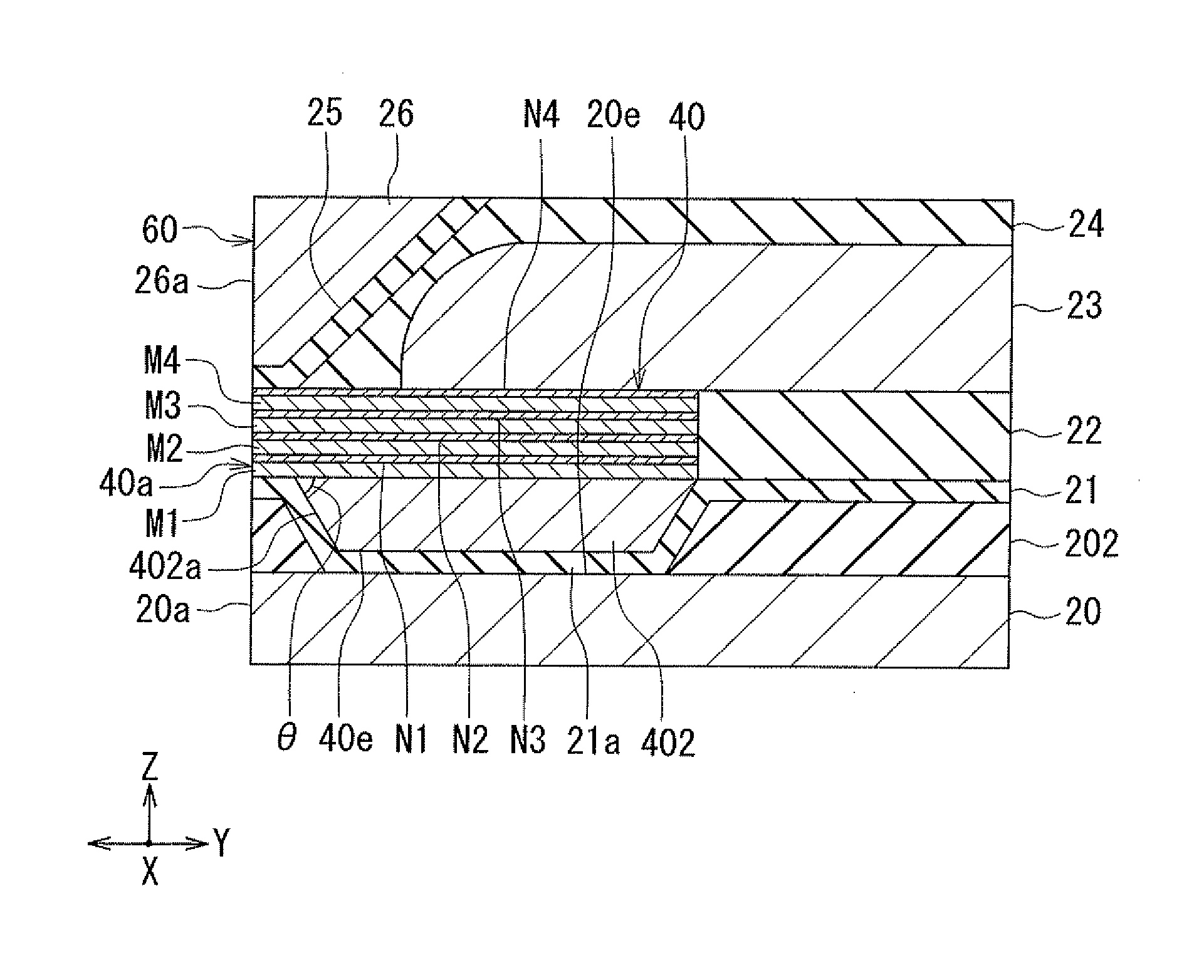
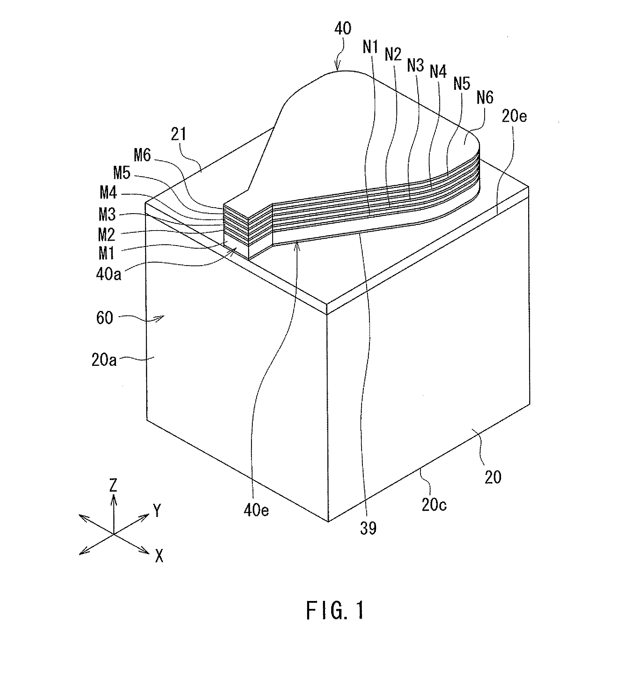
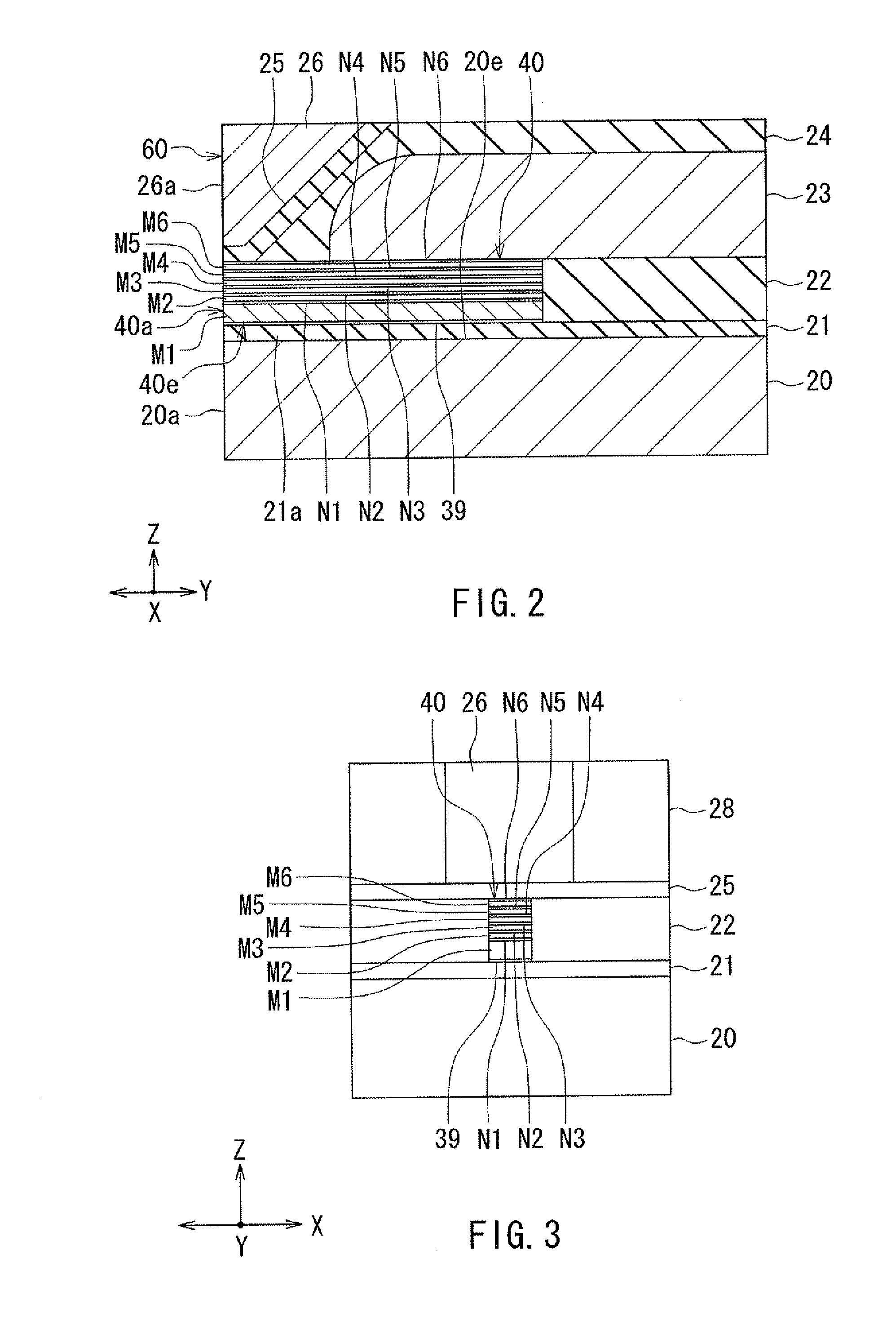
[0128]Reference is now made to FIG. 19 and FIG. 20 to describe a plasmon generator and a thermally-assisted magnetic recording head according to a third embodiment of the invention. FIG. 19 is a perspective view showing the main part of the thermally-assisted magnetic recording head according to the present embodiment. FIG. 20 is a cross-sectional view showing the main part of the thermally-assisted magnetic recording head according to the present embodiment.
[0129]How the plasmon generator 40 according to the present embodiment differs from the first embodiment will now be described. In the plasmon generator 40 according to the present embodiment, the intermediate layer N1 lies on a portion of the top surface of the first metal layer M1, the portion being located in the vicinity of the front end face 40a. The metal layer M2, the intermediate layer N2, the metal layer M3, the intermediate layer N3, the metal layer M4, the intermediate layer N4, the metal layer M5, the intermediate la...
PUM
| Property | Measurement | Unit |
|---|---|---|
| Thickness | aaaaa | aaaaa |
| Dielectric polarization enthalpy | aaaaa | aaaaa |
| Hardness | aaaaa | aaaaa |
Abstract
Description
Claims
Application Information
 - R&D
- Intellectual Property
- Life Sciences
- Materials
- Tech Scout
- Unparalleled Data Quality
- Higher Quality Content
- 60% Fewer Hallucinations
Browse by: Latest US Patents, China's latest patents, Technical Efficacy Thesaurus, Application Domain, Technology Topic, Popular Technical Reports.
© 2025 PatSnap. All rights reserved.Legal|Privacy policy|Modern Slavery Act Transparency Statement|Sitemap|About US| Contact US: help@patsnap.com